
Method For Manufacturing High Purity Tin, Electrowinning Apparatus For High Purity Tin And High Purity Tin

a technology of high purity tin and electrowinning apparatus, which is applied in the direction of electrolysis components, instruments, optics, etc., can solve the problems of high cost of complicated method for manufacturing high purity tin disclosed in patent literature 1, and always taking into the cathode. , to achieve the effect of improving the productivity of tin, reducing manufacturing cost, and high purity tin

Inactive Publication Date: 2016-04-07
JX NIPPON MINING& METALS CORP
View PDF2 Cites 10 Cited by
  • Summary
  • Abstract
  • Description
  • Claims
  • Application Information

AI Technical Summary

Benefits of technology

The present invention provides a method for making high purity tin that reduces manufacturing costs, improves productivity, and reduces α ray emission. Additionally, an electrowinning apparatus for high purity tin is also provided. This results in highly pure tin materials.

Problems solved by technology

Since recent semiconductor devices are highly densified and highly integrated, there is a considerable risk that a soft error may be caused by α rays emitted from materials in the vicinity of bonded semiconductor chips, and therefore, there are demands for technologies capable of obtaining high purity tin with a decreased emission of α rays.
However, the method for manufacturing high purity tin disclosed in Patent Literature 1 is expensive because the mixed acid of fluorosilicic acid and sulfuric acid is used as an electrolytic solution.
Further, the method for manufacturing high purity tin disclosed in Patent Literature 1 is complicated because controlling the temperature of solution in the setting tank is essential.
Furthermore, though Patent Literature 1 employs a method for diluting lead by mixing a refined electrolytic solution and an unrefined electrolytic solution, the apparatus for electrowinning disclosed in Patent Literature 1 does not have a diaphragm between an anode and a cathode, and therefore, there is a possibility that lead leached from the anode is always taken into the cathode.
Accordingly, the purification effect of lead tends to be decreased, and as a whole, the method cannot be said to be of an expected level with regard to making high purity tin despite manufacturing being expensive.
However, Patent Literature 3 only discloses properties relating to the α ray count, but does not particularly disclose impurities such as lead in tin oxide.
Though it is natural that the use of a high purity raw material can produce a high purity material, as disclosed in Patent Literature 4, the lowest α ray count of the deposited tin shown in Examples of Patent Literature 4 is 0.03 cph / cm2, and therefore, Patent Literature 4 cannot achieve an expected level despite the method being expensive.
However, it cannot be said that Patent Literature 5 achieves an expected level of the α ray count of the deposited tin despite the method being expensive, either.
However, in the manufacturing methods proposed in Patent Literatures 6 and 7, a smoothing agent for smoothing electrodeposited tin which is electrodeposited on the surface of a cathode has not been added in order to sufficiently secure the potential difference between tin and lead, and therefore, the electrodeposited tin which is electrodeposited on the surface of the cathode was needle-shaped.
In addition, since electrodeposited tin is needle-shaped, the surface area of electrodeposited tin tends to be large, and when manufacturing an ingot of tin by casting electrodeposited tin in the air, there has been a case where oxidation tends to proceed easily.
As a result, it has been necessary for casting to be performed in a reducing atmosphere such as hydrogen in order to obtain high purity tin, and there has been a case where the productivity cannot be improved sufficiently.

Method used


Image

  • Method For Manufacturing High Purity Tin, Electrowinning Apparatus For High Purity Tin And High Purity Tin
  • Method For Manufacturing High Purity Tin, Electrowinning Apparatus For High Purity Tin And High Purity Tin
  • Method For Manufacturing High Purity Tin, Electrowinning Apparatus For High Purity Tin And High Purity Tin

Examples


example 1

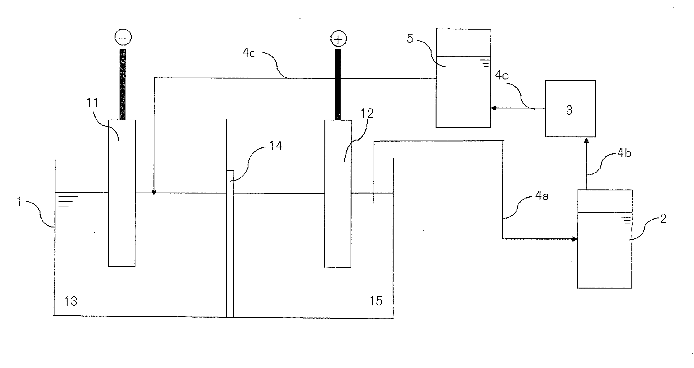
[0066]A predetermined amount of a sulfuric acid solution was added to a cathode side and a dilute sulfuric acid solution of pH 0.5 was added to an anode side of an electrolytic bath of which a cathode and an anode were partitioned by an anion exchange membrane (SELEMION AMV manufactured by ASAHI GLASS CO., LTD.). In addition, hydroquinone was added as an antioxidant into an anode side electrolytic solution such that the concentration was 5 g / L in the electrolytic solution. An anode obtained by casting a raw material for tin and a cathode made of titanium were placed in the electrolytic bath, respectively, and electrolytically leaching was performed at a current density of 2 A / dm2 and a solution temperature of 33° C. to give an electrolytic solution of tin sulfate (with a concentration of tin of 105 g / L).

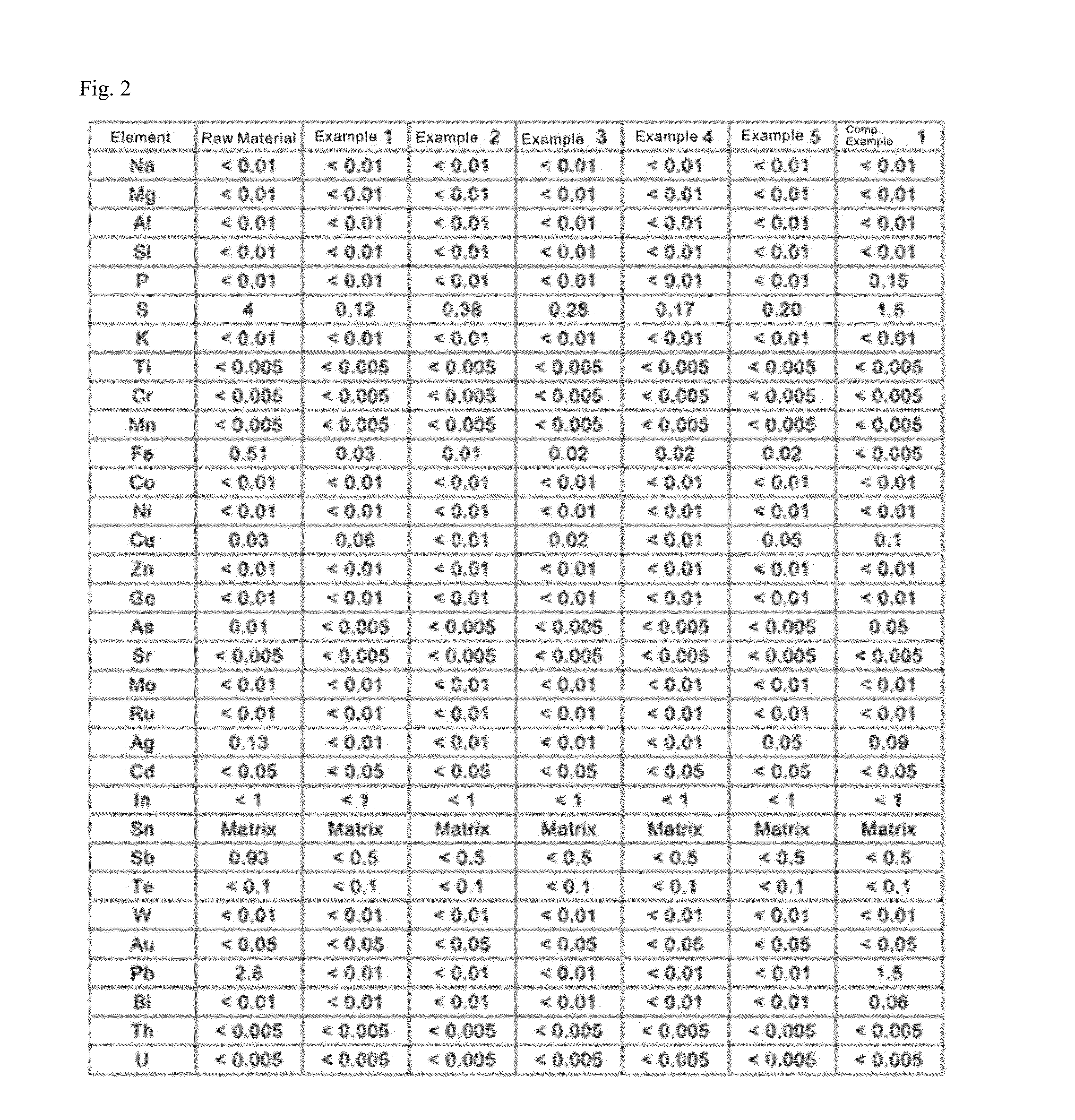
[0067]A result of analysis of the raw material for tin (raw material) used as the anode is shown in FIG. 2.

[0068]A portion of the electrolytic solution in the anode chamber was disch...

example 2

[0072]In Example 1, the concentration of tin in the electrolytic solution in the anode chamber after completing electrowinning was 94 g / L and pH of this solution was pH 0.54. This electrolytic solution in the anode chamber was discharged, and was supplied to the tank for solution purification in which lead is removed. Powdery strontium carbonate was added to the tank for solution purification such that the concentration of strontium carbonate was 5 g / L in the electrolytic solution, and the resulting solution was stirred for 16 hours. After stirring, the electrolytic solution was subjected to solid-liquid separation by sucking filtration in order to remove lead as a precipitate in the electrolytic solution.

[0073]Next, a post treatment solution containing the smoothing agent which had been obtained in the cathode chamber by electrowinning of Example 1 was added back to the anode side of the electrolytic bath such that the reduced amount corresponding to the discharged electrolytic sol...

example 3

[0075]In Example 2, the concentration of tin in the electrolytic solution in the anode chamber was 100 g / L and pH of this solution was pH 0.63 after completing electrowinning. The solution purification processing was performed in a similar manner to Example 2 except that the added amount of strontium carbonate was 10 g / L. The electrolytic solution from which lead had been removed had the concentration of lead of less than 0.1 mg / L.

[0076]Next, a post treatment solution containing the smoothing agent which had been obtained in the cathode chamber by electrowinning of Example 2 was added back to the anode side of the electrolytic bath such that the reduced amount corresponding to the discharged electrolytic solution was supplemented.

[0077]Then, the electrolytic solution from which lead had been removed in the tank for solution purification was added into the cathode side chamber. The smoothing agent added in Example 1 was not decomposed in the cathode chamber in the electrolytic bath a...


PUM

PropertyMeasurementUnit
Fractionaaaaaaaaaa
Fractionaaaaaaaaaa
Fractionaaaaaaaaaa

Abstract

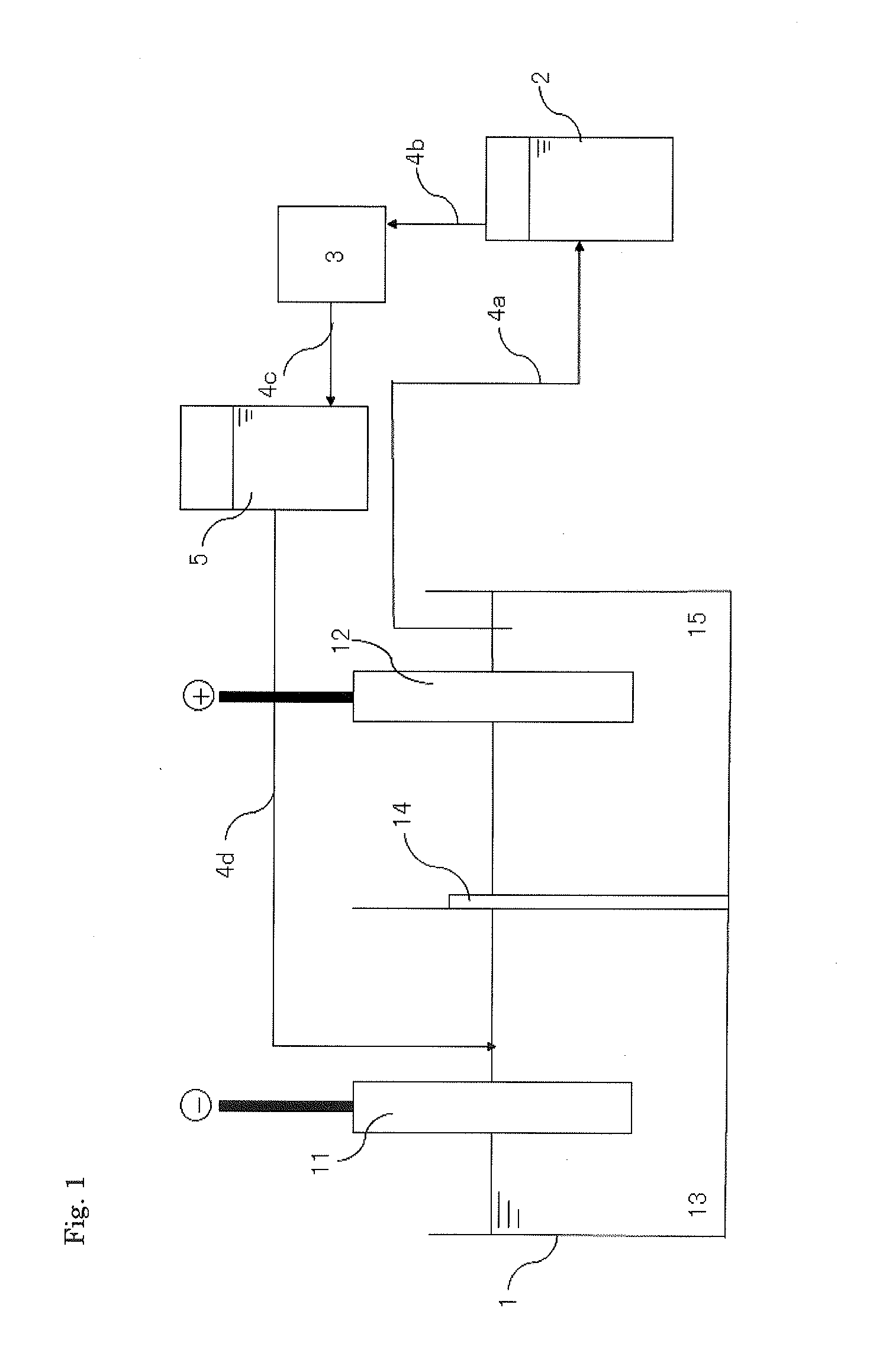
Provided is a method for manufacturing high purity tin including: depositing electrodeposited tin on the surface of a cathode 11 by electrowinning in an electrolytic bath in which a diaphragm 14 is placed between an anode 12 and the cathode 11, by using a raw material for tin as the anode 12 and a leachate obtained by electrolytically leaching the raw material for tin in a sulfuric acid solution as an electrolytic solution, the electrolytic solution containing a smoothing agent for improving a surface property of the electrodeposited tin; discharging the electrolytic solution from the electrolytic bath such that lead in the discharged electrolytic solution is removed; and putting the electrolytic solution from which lead is removed back into the electrolytic bath.

Description

TECHNICAL FIELD[0001]The present invention relates to a method for manufacturing high purity tin, an electrowinning apparatus for high purity tin and high purity tin. More specifically, the present invention relates to a method for manufacturing high purity tin which is capable of manufacturing a plate electrodeposited entity with a low concentration of sulfur and a low concentration of antimony, and is capable of manufacturing high purity tin from the plate electrodeposited entity, and an electrowinning apparatus for high purity tin as well as high purity tin.BACKGROUND ART[0002]Tin has been widely used for manufacturing electronic parts. For example, tin is used for solder materials used for bonding a semiconductor chip and a substrate, bump forming materials used during TAB (tape automated bonding) or during mounting flip chips and semiconductor wiring materials and the like. Since recent semiconductor devices are highly densified and highly integrated, there is a considerable ri...

Claims


Application Information

Patent Timeline
IPC IPC(8): C25C1/14C22C13/00C25C7/06
CPCC25C1/14C22C13/00C25C7/06Y02P10/20
Inventor TAKEMOTO, KOUICHIIMORI, TORUOUCHI, TAKASHITAKAHASHI, HIROFUMI
Owner JX NIPPON MINING& METALS CORP
Learn More