Electroconductive laminate and touch panel using thereof

a technology of electroconductive laminate and touch panel, which is applied in the direction of instruments, other domestic objects, synthetic resin layered products, etc., can solve the problems of deteriorating visibility of interference fringes, generating cohesive failure of the substrate surface, and deteriorating appearance of interference fringes, etc., to achieve excellent hardness, high visibility, and high refractive index

Active Publication Date: 2016-08-18
NIPPON PAINT AUTOMOTIVE COATINGS +1
View PDF3 Cites 5 Cited by
  • Summary
  • Abstract
  • Description
  • Claims
  • Application Information

AI Technical Summary

Benefits of technology

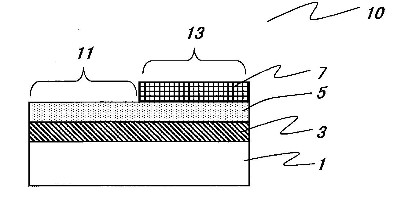
[0023]The electroconductive laminate according to the present invention has a hard coat layer obtained by applying a specific hard coating composition onto a polycarbonate substrate. The hard coat layer according to the present invention has features of excellent hardness, high visibility and stretchability. The hard coat layer according to the present invention also has a high refractive index. Therefore, the present invention has an advantage to prevent the occurrence of interference fringes in case that the hard coat layer according to the present invention is applied onto a high refractive index substrate film such as a polycarbonate film.
[0024]A resin components contained in the hard coating composition according to the present invention also has a technical characteristic of providing a high refractive index, even if the hard coating composition does not substantially include high refractive index materials such as metal oxide. The hard coat layer according to the present invention also has features of excellent stretchability, in addition to excellent hardness and high refractive index.
[0025]The hard coating composition which provides the hard coat layer according to the present invention does not contain a resin component that may volatilize due to heat or pressure applied in the process of manufacturing the touch panel electrode, or not comprise a resin component having a structure that may volatilize by degradation. Therefore, the present invention has an advantage that the inhibition of crystallization of the transparent electrically conductive layer formed on the upper layer is small. In addition, with regard to adhesion, adhesion to a polycarbonate substrate and a layer formed on the upper layer is improved together. Therefore, even in a higher level of an adhesion test (severe adhesion test), high adhesion can be ensured.
[0026]The hard coating composition for forming the hard coat layer of the present invention contains a urethane acrylate having an ester structure. Thus, as described-above, even in a higher level of the adhesion test (severe adhesion test), high adhesion can be ensured. The hard coat layer of the present invention also provides a technical effect that the occurrence of interference fringes is prevented, even in case that the hard coat layer is applied onto a polycarbonate substrate. In general, when difference in refractive index between a polycarbonate substrate and a hard coat layer is large, the occurrence of interference fringe is observed. However, the hard coating layer of the present invention provides a technical effect that the occurrence of interference fringes is prevented, even in case that the hard coat layer has a refractive index within a range of 1.535 to 1.545.

Problems solved by technology

On the other hand, the application of a transparent hard coat layer onto a substrate causes a problem of the appearance of interference fringes.
The appearance of interference fringes deteriorates visibility.
Thus, when a pyrolysis is generated, it may become a volatile component and it tends to inhibit a crystallization of the transparent conductive film formed on the hard coat layer (typically an ITO film).
But, a higher level of an adhesion test (severe adhesion test) will generate a problem that a cohesive failure of the substrate surface is generated.

Method used


Image

  • Electroconductive laminate and touch panel using thereof
  • Electroconductive laminate and touch panel using thereof
  • Electroconductive laminate and touch panel using thereof

Examples


production example 1

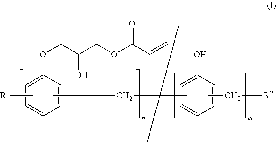
Production of a Phenolic Novolac Acrylate (1)

[0156]In a reaction vessel equipped with a stirrer, a thermometer, a dropping funnel and a reflux apparatus, 150 g of phenol novolac resin (a weight average molecular weight of 700 to 900, an epoxy equivalent of 150 to 200) and 550 g of epichlorohydrin were mixed, and 110 g of an aqueous solution of sodium hydroxide (48.5%) was added dropwise for 2 hours under a temperature of 100° C. and a reduced pressure of 100 to 200 mmHg.

[0157]After the reaction was finished, a reaction temperature of the reaction mixture was lowered to a room temperature, and excess amounts of an aqueous solution of sodium hydroxide were neutralized with an acid, then the reaction mixture was heated under a reduced pressure to remove excess amounts of epichlorohydrin.

[0158]Next, the resulting reaction mixture was dissolved in methyl isobutyl ketone, and a salt of byproduct was removed by water filtration to obtain a solution of phenol novolac epoxy resin.

[0159]To th...

production example 2

Production of a Phenolic Novolac Acrylate (2)

[0161]In a reaction vessel equipped with a stirrer, a thermometer, a dropping funnel and a reflux apparatus, 150 g of phenol novolac resin (a weight average molecular weight of 900 to 1100, an epoxy equivalent of 150 to 200) and 550 g of epichlorohydrin were mixed, and 110 g of an aqueous solution of sodium hydroxide (48.5%) was added dropwise for 2 hours under a temperature of 100° C. and a reduced pressure of 100 to 200 mmHg. After the reaction was finished, a reaction temperature of the reaction mixture was lowered to a room temperature, and excess amounts of an aqueous solution of sodium hydroxide were neutralized with an acid, then the reaction mixture was heated under a reduced pressure to remove excess amounts of epichlorohydrin.

[0162]Next, the resulting reaction mixture was dissolved in methyl isobutyl ketone, and a salt of byproduct was removed by water filtration to obtain a solution of phenol novolac epoxy resin.

[0163]To the re...

production example 3

Production of Polyfunctional Urethane Acrylate

[0165]In a four-necked flask of 1 L equipped with a thermometer, a cooling tube, and a stirrer, 341 g of polycarbonate diol of 1,5-pentanediol and 1,6-hexanediol (manufactured by Asahi Kasei Chemicals Corporation, PCDL T-5652, number average molecular weight: 2000), 17 g of acrylic acid adduct of 1,6-hexanediol diglycidyl ether (manufactured by Showa Highpolymer, Ripoxy SP-16LDA), 43 g of isophorone diisocyanate, 0.2 g of dibutyltin dilaurate (reaction catalyst), and 400 g of methyl ethyl ketone (organic solvent) were added, and reaction was performed while stirring at 70° C. for 24 hours. After the reaction, it was confirmed that no isocyanate residue was observed by infrared absorption spectrum. As a result, unsaturated group-containing urethane resin (polyfunctional urethane acrylate) having 30,000 of a number-average molecular weight and a degree of unsaturation of 0.23 mol / kg was obtained. The obtained Polyfunctional urethane acryla...


PUM

PropertyMeasurementUnit
refractive indexaaaaaaaaaa
thicknessaaaaaaaaaa
average primary particle diameteraaaaaaaaaa

Abstract

The present invention is an electroconductive laminate characterized in that the hard coat layer is formed from a hard coating composition which contains (A) a phenolic novolac acrylate having two or more acrylate groups, (B) a bisphenol structure-containing diacrylate having 2 to 4 moles of alkylene oxide structure with two or three carbon atoms in each molecule, (C) a polyfunctional acrylate having three or more acrylate groups, and (D) a polyfunctional urethane acrylate having three or more acrylate groups and an ester structure.

Description

TECHNICAL FIELD[0001]The present invention relates to an electroconductive laminate in which a hard coat layer and an electrically conducting layer are formed on at least one surface of a polycarbonate substrate, in particular, an electroconductive laminate having a hard coat layer that has stretchability in addition to high visibility and excellent hardness, while exhibiting excellent adhesion toward a polycarbonate substrate, and a touch panel using thereof.BACKGROUND OF THE INVENTION[0002]A liquid crystal display device has advantages such as thinness, lightweight, low power consumption and so on, and is widely used in various technical fields such as computers, word processors, television sets, mobile phones, handheld terminal devices and so on. In addition, so-called touch panels of such liquid crystal display devices having a mechanics of manipulation by touch on their screen are spreading rapidly. The touch panels are widely used in mobile phones like smart phones, tablet com...

Claims


Application Information

Patent Timeline
Patent Type & Authority Applications(United States)
IPC IPC(8): G06F3/044
CPCG06F3/041G06F3/044G06F2203/04103B32B27/08B32B27/308B32B27/365B32B27/42B32B2255/10B32B2255/26B32B2255/28B32B2264/10B32B2307/202B32B2307/412B32B2307/536B32B2307/54B32B2307/744B32B2457/208C09D123/06
Inventor IMAMURA, KOICHISASAKI, ATSUSHIKOBAYASHI, KAZUHITONAKATA, YUSUKE
Owner NIPPON PAINT AUTOMOTIVE COATINGS
Why Eureka
Try Eureka