
Kinetic batteries

a technology of kinetic batteries and batteries, applied in the field of kinetic batteries, can solve the problems of shortcoming of conventional battery manufacturing approaches

Inactive Publication Date: 2018-05-17
WORCESTER POLYTECHNIC INSTITUTE
View PDF1 Cites 27 Cited by
  • Summary
  • Abstract
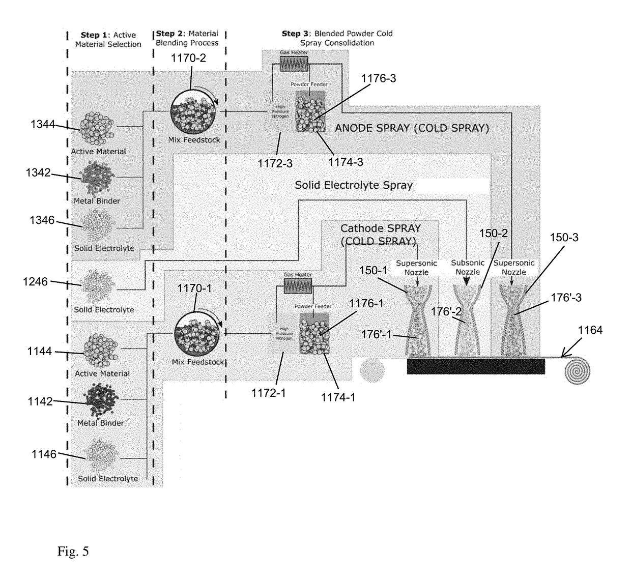
  • Description
  • Claims
  • Application Information

AI Technical Summary

Benefits of technology

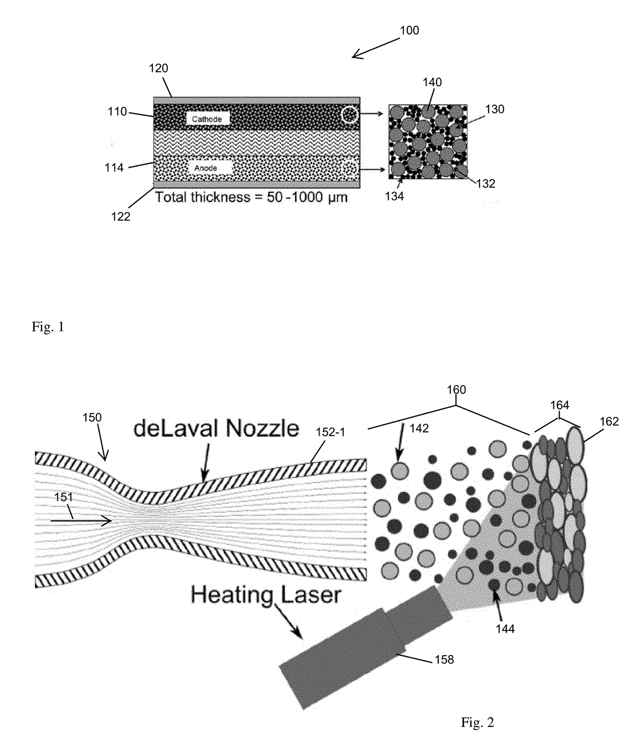
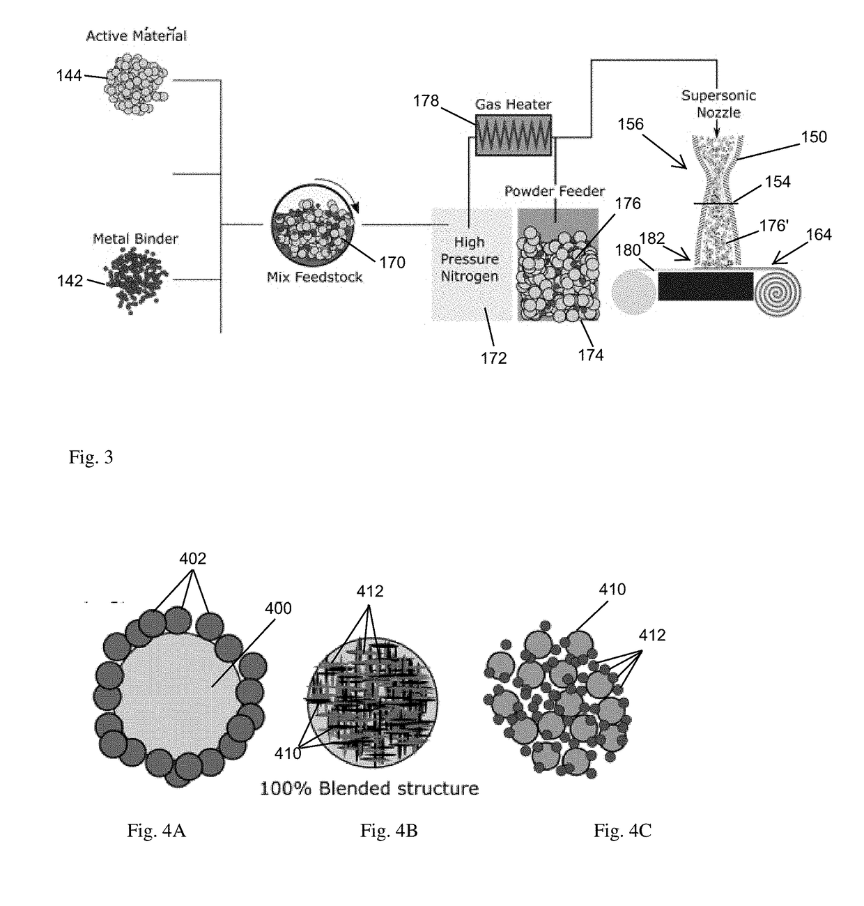
[0003]A rechargeable lithium-ion (Li-ion) battery employs a solvent-less, low temperature approach to battery manufacturing that forms charge material from kinetic energy of high velocity particles impelled into an aggregation such that bombardment of the particles against other particles in the aggregation forms a charge conveying structure. High velocity bombardment from a carrier gas nozzle accumulates an active charge material (active material) and metal binder in a layered arrangement for the finished battery. This metal binder serves as the structural binding agent, the electron conducting agent, and the deformation phase critical for cohesion of the sprayed agglomerate particles. Preparation of the particles, such as by ball milling or freeze drying, arranges particle agglomerations. The particle agglomerations, when impelled against other agglomerations or a current collector, forms a layer of cathodic, anodic or electrolytic battery material. The metallic binder conveys charge for mitigating or eliminating a need for a planar current collector underlying the sprayed layer. The resulting layers are suitable for battery operation, and are manufactured in an absence of any solvent drying or disposal.
[0004]Configurations herein are based, in part, on the observation that lithium ion batteries are achieving widespread popularity for mobile power needs of electric vehicles and personal devices. Rechargeable power supplies such as lithium ion batteries are generally sought for their high energy density and their ability to deliver current at a high rate. Unfortunately, conventional approaches to battery manufacturing suffer from the shortcoming of solvent based approaches that impose toxicity and environmental concerns for use, handling and disposal of the solvent. Accordingly, configurations herein substantially overcome the toxicity and handling shortcomings by providing a spray based manufacturing method that forms cathode, anode and electrolyte layers from high velocity particle spraying that forces the charge materials into a conformant arrangement conducive to charge generation and transport. Further, the flexibility of particle spray deposition to electrode fabrication allows architecture of non-standard battery geometries to suit implementation specific volume or electrochemical constraints.
[0005]A particle stream of precision milled particles engages and accumulates the particles into a distribution suitable for battery operation, as successive particles are forced together in a binding arrangement sufficient for charge transport. Spraying, as employed herein, refers to impelling or forcing the particle agglomerations though a nozzle using a pressurized carrier gas such that they bombard an accumulation surface and build a thickness as bombarded by successive agglomerations due to deformation and ductility of the agglomerations. In contrast to conventional uses of cold spray, the particle preparation forms agglomerations that, in conjunction with impelling from the nozzle, aggregate based on the ductile nature of the agglomerations into a density suitable for battery usage. In this manner, a layer of charge materials may be deposited onto a current collector for subsequent rolling, folding, or layering for a finished battery, or multiple layers defining cathode, anode and electrolyte regions may be continuously sprayed as a complete structure without a need for a conductive current collector. Each layer of either cathode, anode, or electrolyte region may be controlled for composition, porosity, and geometry by altering the powder feedstock and spray conditions. Doing so allows for customization of the charge / discharge profiles of the battery cell.
[0006]The disclosed approach presents a solvent-less approach to battery manufacturing in which the core constituents are a powdered material. The process takes an active material blended with a metal binder and sprays the material at supersonic speeds onto a current collector. Additional additives such as carbon black, stearic acid, or a solid electrolyte may be blended with the powder and sprayed for varying benefits. The end result is a battery electrode produced at lower costs, with greater control over the battery internal geometry and overall thickness. This enables higher capacity batteries, and batteries that can operate at higher charge / discharge rates with reduced overall heating. Alternate configurations include multiple layer sprays for forming respective cathode, electrolyte and anode layers, and an absence of an underlying current collector achieved by dispersing conductive particles in the sprayed material.
[0007]In one configuration, the kinetically formed batteries (kinetic batteries) may employ solid state manufacturing such as cold spray to bind lithium oxide or phosphate particles with a metallic phase to create the cathode. This approach decreases interface resistances, enables local control of energetic properties, and allows for manufacture of custom-sized cathodes without the inactive materials such as binders and toxic solvents used in traditional manufacturing.
[0008]Other approaches may eliminate the planer current collector, typically a copper or aluminum sheet, and deposit multiple layers in succession for cathode, electrolyte and anode layers in one pass from multiple nozzle rows. Degrading or disintegrating polymers may be incorporated to assist particle flow and adhesion.

Problems solved by technology

Unfortunately, conventional approaches to battery manufacturing suffer from the shortcoming of solvent based approaches that impose toxicity and environmental concerns for use, handling and disposal of the solvent.

Method used


Image

  • Kinetic batteries
  • Kinetic batteries
  • Kinetic batteries

Examples


Embodiment Construction

[0018]Configurations below depict an example of battery construction. Construction employs sprayed particulate matter, such as high pressure cold spray, low pressure cold spray, laser assisted cold spray or similar additive manufacturing technique. In contrast to conventional solvent based approaches, using a slurry of charge material and binder liquids followed by evaporation, the active material is sprayed with a conductive metal binder and optional solid electrolyte polymer powder to form a proper density from the spray velocity.

[0019]Formation of the battery structure may include depositing either a cathodic or anodic active material onto a current collector, or a “collector-less” arrangement which forms a cathode, electrolyte and anode layer in succession and in the absence of a current collector.

[0020]The first configurations overcome conventional shortcomings of solvent based polymeric binders by combining a cathode material and a metallic binder to form a powdered combinatio...


PUM

PropertyMeasurementUnit
sizeaaaaaaaaaa
sizeaaaaaaaaaa
thickaaaaaaaaaa

Abstract

A rechargeable lithium-ion (Li-ion) battery employs a solvent-less, low temperature approach to battery manufacturing that forms charge material from kinetic energy of high velocity particles impelled into an aggregation such that bombardment of the particles against other particles in the aggregation forms a charge conveying structure. High velocity bombardment from a carrier gas nozzle accumulates an active charge material (active material) and metal binder in a layered arrangement for the finished battery. Preparation of the particles, such as by ball milling or freeze drying, arranges particle agglomerations. The particle agglomerations, when impelled against other agglomerations or a current collector, forms a layer of cathodic, anodic or electrolytic battery material. The metallic binder conveys charge for mitigating or eliminating a need for a planar current collector underlying the sprayed layer. The resulting layers are suitable for battery operation, and are manufactured in an absence of any solvent drying or disposal.

Description

RELATED APPLICATIONS[0001]This application claims the benefit under 35 U.S.C. § 119(e) of U.S. Provisional Patent Application No. 62 / 423,237, filed Nov. 17, 2016, entitled “KINETIC BATTERIES,” and U.S. Provisional Patent Application No. 62 / 550,846, filed Aug. 28, 2017, entitled “SPRAYED LAYER BATTERY CONSTRUCTION,” both incorporated herein by reference in entirety.BACKGROUND[0002]Rechargeable batteries, such as lithium ion batteries are manufactured by spreading, rolling, and drying a slurry of conductive polymer binder, toxic solvent, conductive agent, and lithium-based oxide (or other ceramic) particles onto a conductive current collector to form a functional cathode. This limits the size, geometry, and energetic properties of the resulting batteries. The prevailing conventional method for electrode production, known as tape casting, depends on mixing a slurry of at least four ingredients, spreading the mixture across the current collector using a Doctor blade, calendaring the coa...

Claims


Application Information

Patent Timeline
Patent Type & Authority Applications(United States)
IPC IPC(8): H01M4/04H01M4/62H01M4/525H01M4/587C23C24/04C23C24/06H01M4/505H01M4/485H01M4/58H01M4/38H01M4/40
CPCH01M4/0419H01M4/625H01M4/525H01M4/587C23C24/045C23C24/06H01M4/626H01M4/505H01M4/485H01M4/5825H01M4/382H01M4/405H01M4/387C23C24/04H01M4/1391H01M4/1393H01M4/1395H01M4/1397H01M4/624Y02E60/10
Inventor BIRT, AARON M.APELIAN, DIRAN
Owner WORCESTER POLYTECHNIC INSTITUTE
Learn More