

Organic electroluminescent device
a technology of electroluminescent devices and organic materials, which is applied in the direction of organic chemistry, luminescent compositions, semiconductor devices, etc., can solve the problems of material deterioration, low thermal resistance, and confined excitons generated within the luminous layer, and achieve high hole mobility, and excellent electron injection/transport performance
- Summary
- Abstract
- Description
- Claims
- Application Information
AI Technical Summary
Benefits of technology
Problems solved by technology
Method used
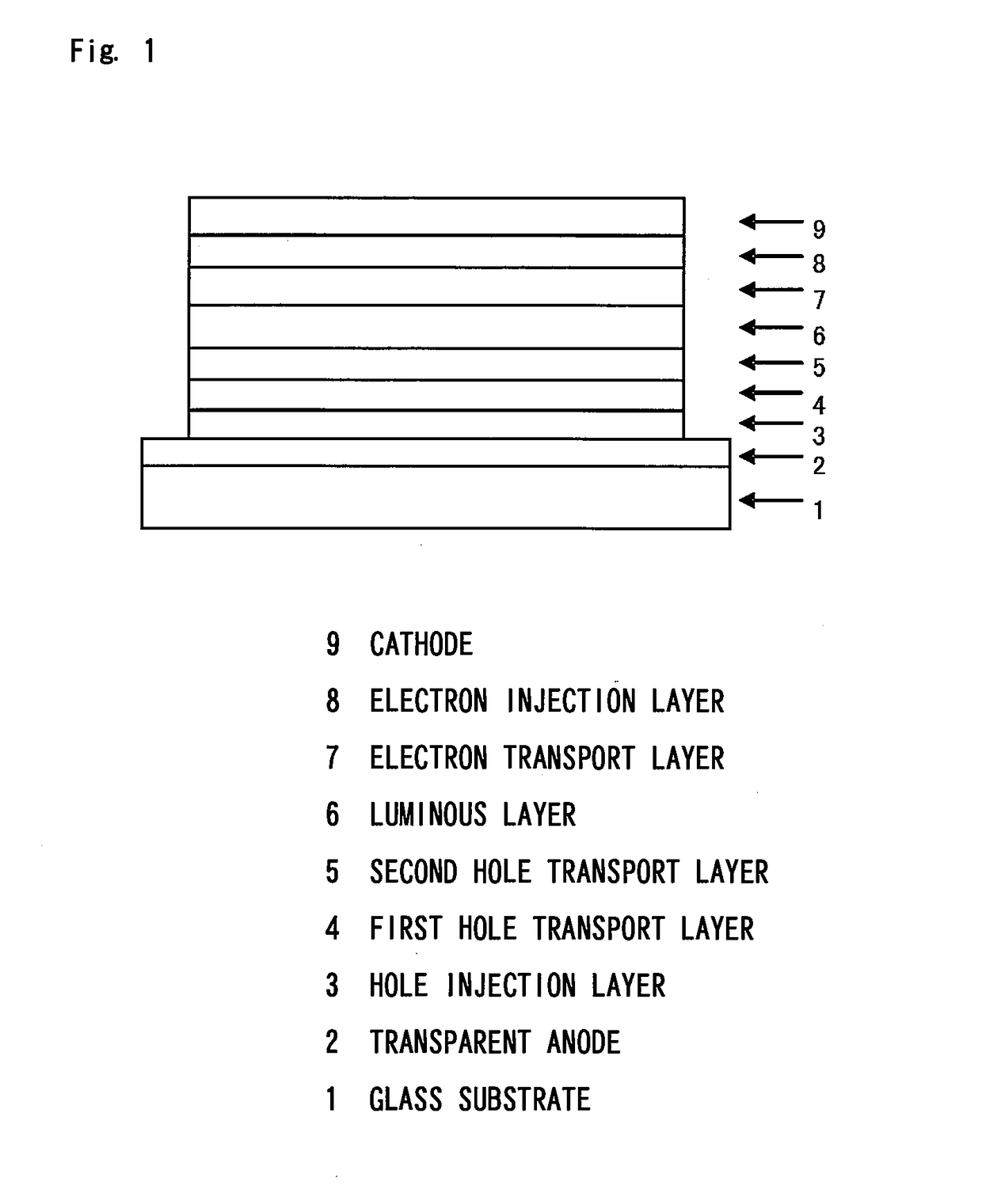
Image

Examples
synthesis example 1
Synthesis of 4,4″-bis{(9,9-dimethyl-9H-fluoren-2-yl)-phenylamino}-1,1′: 3′,1″-terphenyl
[0324]
A nitrogen-purged reaction vessel was charged with8.81 g,4,4″-dibromo-1,1′:3′,1″-terphenyl2-(phenylamino)-9,9-dimethyl-9H-fluorene13.6 g,tert-butoxysodium5.12 g,tris(dibenzylideneacetone)dipalladium0.33 g,a 50% (w / v) toluene solution of tri-tert-butylphosphine0.63 ml,andtoluene 150 ml.
The charged contents were heated, refluxed for 2 hours by stirring, and allowed to cool to prepare a reaction liquid. Then, methanol was added to the reaction liquid, and the resulting precipitate was collected by filtration. The precipitate was dissolved by heating in chlorobenzene, and the solution was subjected to adsorption purification using silica gel. Then, adsorption purification using activated clay was performed whereafter crystallization using a chlorobenzene / methanol mixed solvent was carried out. Then, reflux cleaning using methanol was performed. As a result, 16.25 g (yield 90%) of Compound 1-34 w...
synthesis example 2
Synthesis of 4,4″-bis{(triphenylen-2-yl)-phenylamino}-1,1′;4′,1″-terphenyl
[0329]Reactions were performed under the same conditions as in Synthesis Example 1, except that[0330]4,4″-diiodo-1,1′;4′,1″-terphenyl
was used instead of[0331]4,4″-dibromo-1,1′:3′,1″-terphenyl, and[0332](triphenylen-2-yl)-phenylamine
was used instead of[0333]2-(phenylamino)-9,9-dimethyl-9H-fluorene.
As a result, 11.4 g (yield 74%) of Compound 1-88 was obtained as a white powder.
[0334]For the resulting white powder, its structure was identified using NMR. In 1H-NMR (THF-d8), the following signals of 44 hydrogens were detected.
[0335]δ (ppm)=8.72-8.62 (8H)[0336]8.45 (2H)[0337]8.36 (2H)[0338]7.75 (4H)[0339]7.70-7.21 (26H)[0340]7.09 (2H)
synthesis example 3
Synthesis of 4,4″-bis{N-(2-phenyl-biphenyl-4-yl)-N-phenylamino}-1,1′:4′,1″-terphenyl
[0341]
A nitrogen-purged reaction vessel was charged with13.1 g,N-(2-phenyl-biphenyl-4-yl)-N-phenylamine4,4″-diiodo-1,1′:4′,1″-terphenyl20.0 g,copper powder0.18 g,potassium carbonate11.3 g,3,5-di-tert-butylsalicylic acid0.70 g,sodium bisulfite0.86 g,anddodecylbenzene 30 ml.
The charged contents were heated, stirred for 24 hours at 210° C., and allowed to cool, thereby obtaining a mixture. To the mixture, 30 ml of xylene and 60 ml of methanol were added, whereafter precipitated solids were collected by filtration. The resulting solids were dissolved in toluene, and the solution was subjected to adsorption purification using silica gel. Then, crystallization using ethyl acetate, and crystallization using methanol were performed. Then, purification by recrystallization using chlorobenzene was performed. Further, reflux cleaning using 200 ml of methanol was performed. As a result, 17.0 g (yield 72%) of Co...
PUM
| Property | Measurement | Unit |
|---|---|---|
| Volume | aaaaa | aaaaa |
| Volume | aaaaa | aaaaa |
| Volume | aaaaa | aaaaa |
Abstract
Description
Claims
Application Information