
Pyrolysis reactor with optimized reaction sequencing

Inactive Publication Date: 2018-12-06
DEMENTEV ALEXANDER
View PDF0 Cites 1 Cited by
  • Summary
  • Abstract
  • Description
  • Claims
  • Application Information

AI Technical Summary

Benefits of technology

The present invention provides an apparatus for making heat to quickly process carbon-based materials. It has a reactor that heats surfaces while the material is in contact with them. This process breaks down the material into gas, oil, and solid particles. The exhaust gas contains inorganic particles, and there is ash from the process.

Problems solved by technology

The undesirable phenomenon is that fine particles accumulate on solid surface of the reactor, and cause blockage thereof after a period of time.
However, as the temperature level of operation during pyrolysis increases, the number of construction materials which can be used is drastically reduced.
In the range of 1500 to 2000° C. and higher, there are no readily available materials which can be economically used, have the good mechanical properties required, resist the attack of hydrogen, carbon and hydrocarbons, and also have oxidation resistance over long periods of operating time.
High temperature reactions and processes typically require more complex, costly, and specialized equipment to tolerate the intense heat and physical stress conditions, and leads to lowering the upper limits of temperature for many of the processes and facilities.
In addition to physical temperature limitations for reactor materials, many prior art reactor materials that are inert at lower temperatures may become susceptible to chemistry alterations at high temperature, leading to premature equipment degradation.
Further complicating the material stability and reliability issue has been exposure to large, cyclic temperature swings encountered during many pyrolysis processes.
Changes in temperature and feedstock flow can impose severe physical strength and toughness demands upon the materials at high temperature.
Material life expectancy at high temperature can be severely limited.
Reactor component functions and shapes have been limited for high severity services.
The reviewed arts are demonstrated that the coating has only modest adherence and frequently suffers from partial or fatal barrier spallation or thermal shock cracking after relatively short periods of exposure to high temperature.
This causes quality control and adherence problems.
Moreover, the method of application required to produce the graded layer is tedious.
The reviewed arts are void of teaching how to prepare or select a material having a range of properties that are suitable for use in constructing a furnace for performing substantially continuous, cyclical, high temperature pyrolysis chemistry.
The studied art is believed to be similarly deficient at revealing materials suitable for complex, irregular, or functionally-shaped reactor components.
Lack of materials availability and selection criteria for identifying the materials for use in the reactive and most severe temperature regions of a reactor system is one of the most critical remaining issues in design and large-scale commercial operation of such reactors and processes.
In addition the pyrolysis process is difficult to control sufficiently to ensure feedstock distribution, aeration and to avoid bridging the reactor.
The process according to the prior art permits the use of a reactor, which will take loose shredded feedstock with higher moisture content; this has a major impact on cost and efficiency.
A recurring problem in methods and apparatus for the pyrolysis processes is the generation of ash that tends to fuse into irregular-sized chunks, known as slag, the formation of which tends to block gas passageways and so reduce the efficiency of the pyrolysis of the solid waste materials.
Another common problem which reduces pyrolysis efficiency is the buildup of condensates of tar and resin, resulting in blinding and otherwise restricting filters, grates, and gas passageways.
Still another problem in the art is the production of an off gas from such solid waste pyrolysis that contains insufficient concentrations of combustible gases to comprise a useful fuel product.

Method used


Image

  • Pyrolysis reactor with optimized reaction sequencing
  • Pyrolysis reactor with optimized reaction sequencing
  • Pyrolysis reactor with optimized reaction sequencing

Examples


Embodiment Construction

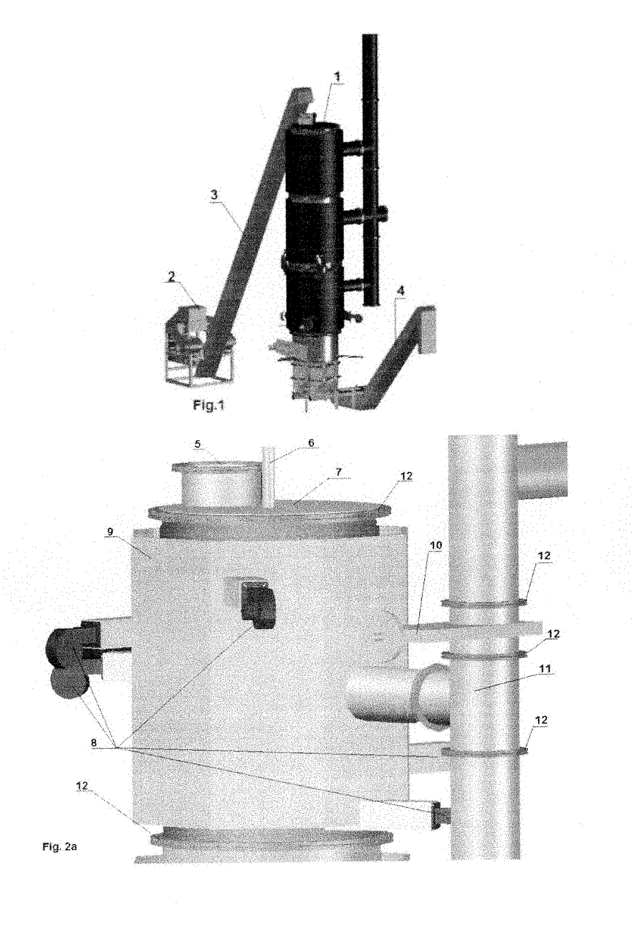
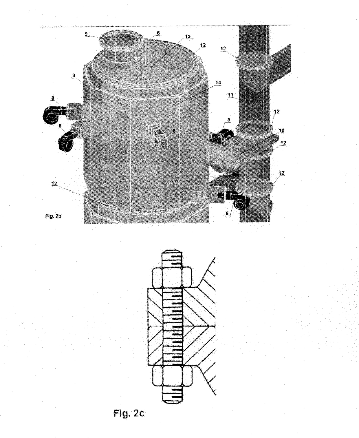
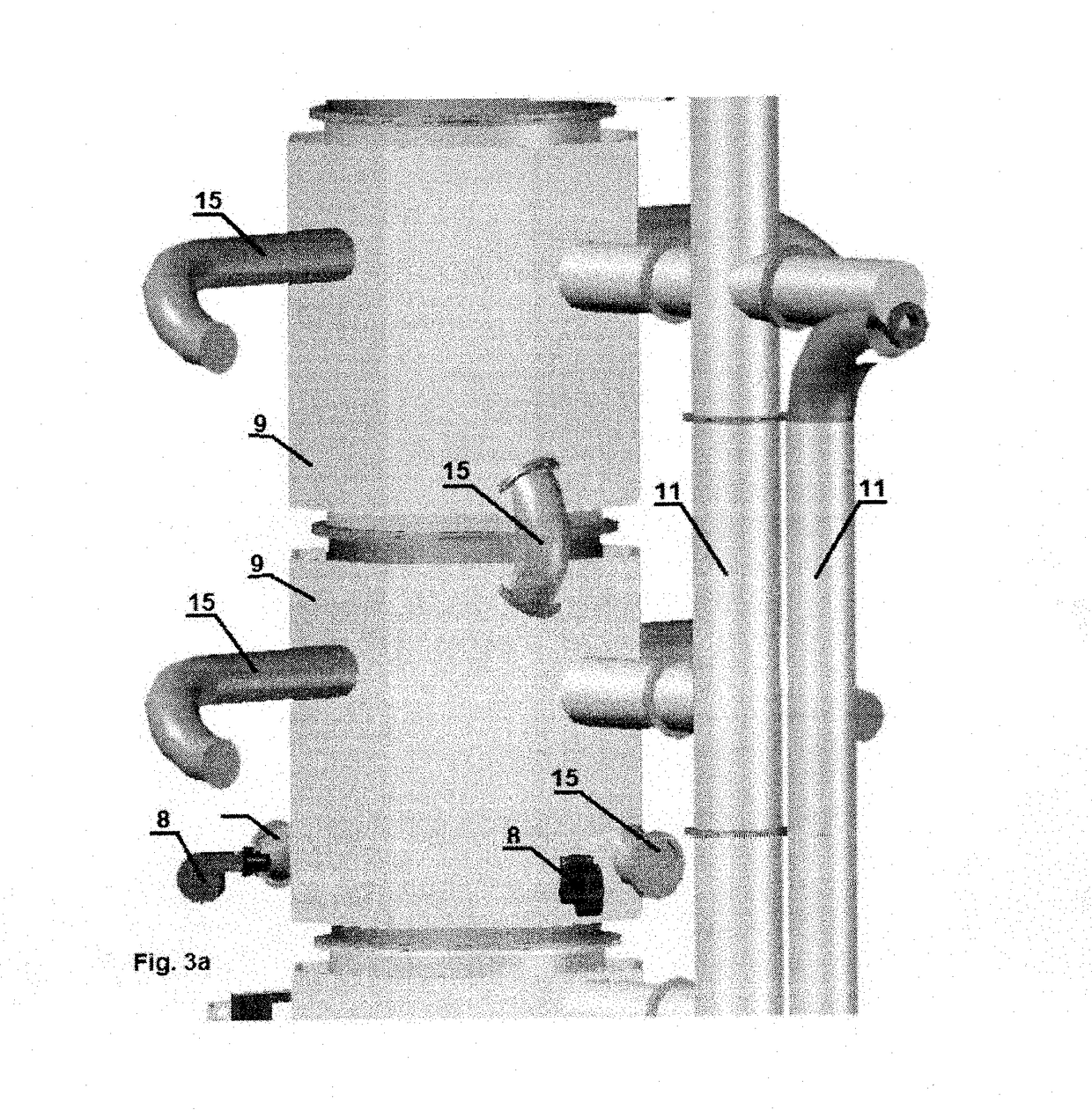
[0036]Specific details of several embodiments of the technology are described below with reference to FIGS. 1-4. Other details describing well-known structures and systems often associated with pyrolysis reactors have not been set forth in the following disclosure to avoid unnecessarily obscuring the description of the various embodiments of the technology. Many of the details, dimensions, angles, and other features shown in the Figures are merely illustrative of particular embodiments of the technology. Accordingly, other embodiments can have other details, dimensions, angles, and features without departing from the spirit or scope of the present technology. A person of ordinary skill in the art, therefore, will accordingly understand that the technology may have other embodiments with additional elements, or the technology may have other embodiments without several of the features shown and described below with reference to FIGS. 1-4.

[0037]For the purpose of this description the p...


PUM


Abstract

System and method for processing pyrolyzable materials in order to recover usable end products are disclosed. The pyrolysis process comprises a number of stages. First pre-treating is to reduce moisture content to approximately 15%. Second is to optimize the volatile organic under the heat and vacuum. This treatment stage is carried out at the temperature between 350 to 400° C. Next, the material is treated with heat and vacuum to produce hot gas and solid carbon residue. This stage is carried out at the temperature up to 800° C. The solid carbon residue can be separated from the hot gas, the volatile organic materials condensed to produce liquid hydrocarbon and gas products. Pyrolysis processes and system according to the present invention are able to thermally decompose carbon-containing materials, including, but not limited to, tires and other rubber-containing materials, hydrocarbon-containing products including pyrolysis oil, used oil and lubricants, organic wastes and alike, carbon containing minerals like brown and bituminous coal, oil shale and oil bearing schists. System and pyrolysis methods according to aspects of the present invention may be successful on a commercial scale.

Description

BACKGROUND OF THE INVENTION[0001]The invention relates to a device for subjecting carbon contained materials to pyrolysis, which device comprises: a reactor with a housing and a reactor space present therein; a first feed for contained materials material or other organic material connecting to the heated up to 400° C. upper zone of this reactor space; a second feed for heated space, connected to the upper side of this reactor space; a first discharge for pyrolysis gas connecting to the upper zone of this reactor space at a distance from the first feed; and a second discharge connecting to the middle zone of this reactor space; and discharge for solid material, for instance carbon material, connecting to the underside of this reactor space. Such a reactor is known in many embodiments from, among others, U.S. Pat. No. 1,777,449, U.S. Pat. No. 3,507,929 and U.S. Pat. No. 4,210,491.[0002]In pyrolysis process wherein a hydrocarbon containing mixture is heated to decomposition or cracking...

Claims


Application Information

Patent Timeline
IPC IPC(8): C10B49/16C10G1/10C10G1/02C10B1/04C10B45/00C10B53/07C10B53/06C10B53/02C10B41/00
CPCC10B49/16C10G1/10C10G1/02C10B1/04C10B41/00C10B53/07C10B53/06C10B53/02C10B45/00C10B47/06C10B47/18C10B53/00C10B53/04Y02E50/10Y02P20/143
Inventor DEMENTEV, ALEXANDER
Owner DEMENTEV ALEXANDER
Learn More