
Integrated pyrolysis and hydrocracking units for crude oil to chemicals

a technology of crude oil and hydrocracking, applied in the direction of hydrocarbon oil treatment, hydrocarbon oil treatment products, thermal non-catalytic cracking, etc., can solve the problems of not meeting fuel specifications and significant yield loss, and achieve effective and efficient hydrocracking of heavier portions, reduce capital and energy requirements, and reduce coking and fouling

Active Publication Date: 2019-01-24
LUMMUS TECH LLC
View PDF2 Cites 13 Cited by
  • Summary
  • Abstract
  • Description
  • Claims
  • Application Information

AI Technical Summary

Benefits of technology

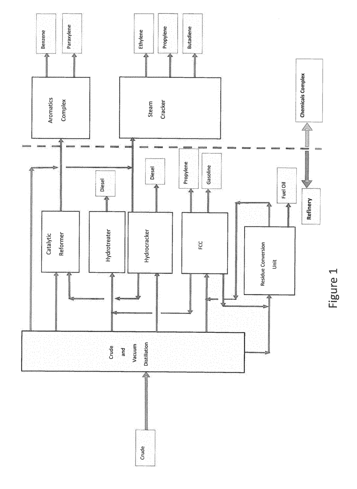
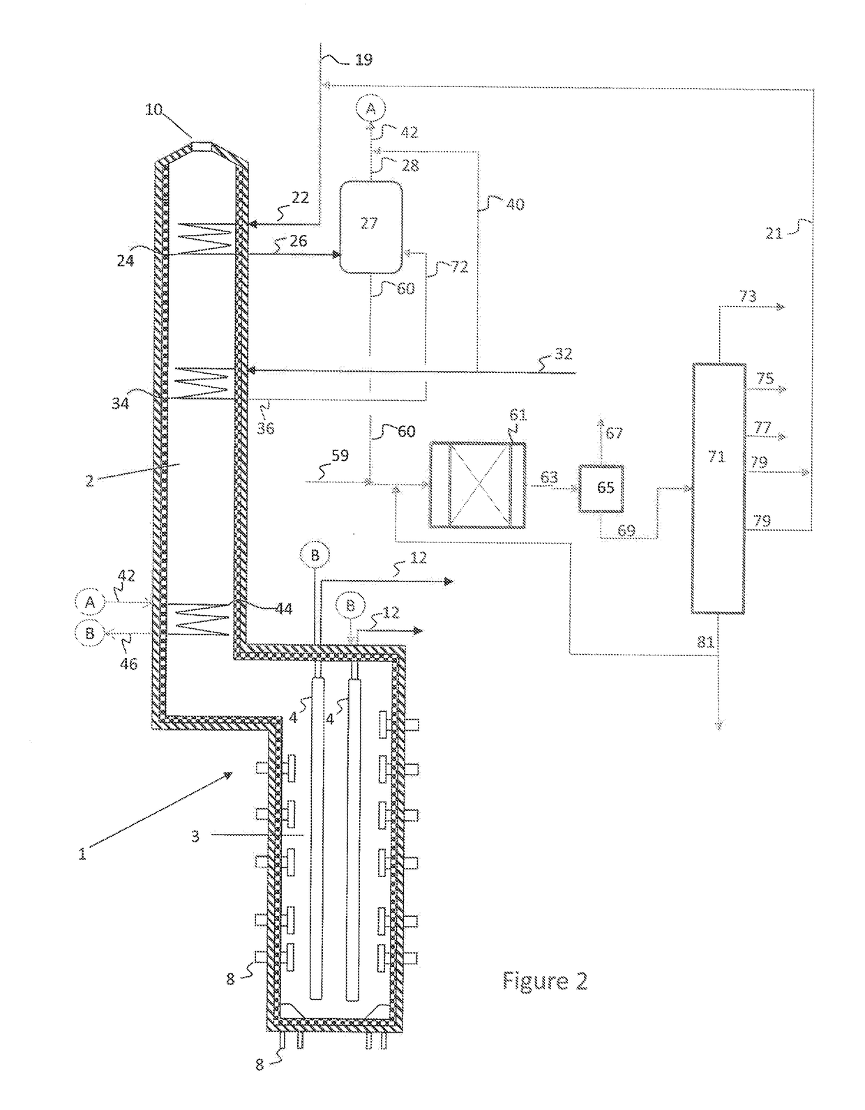
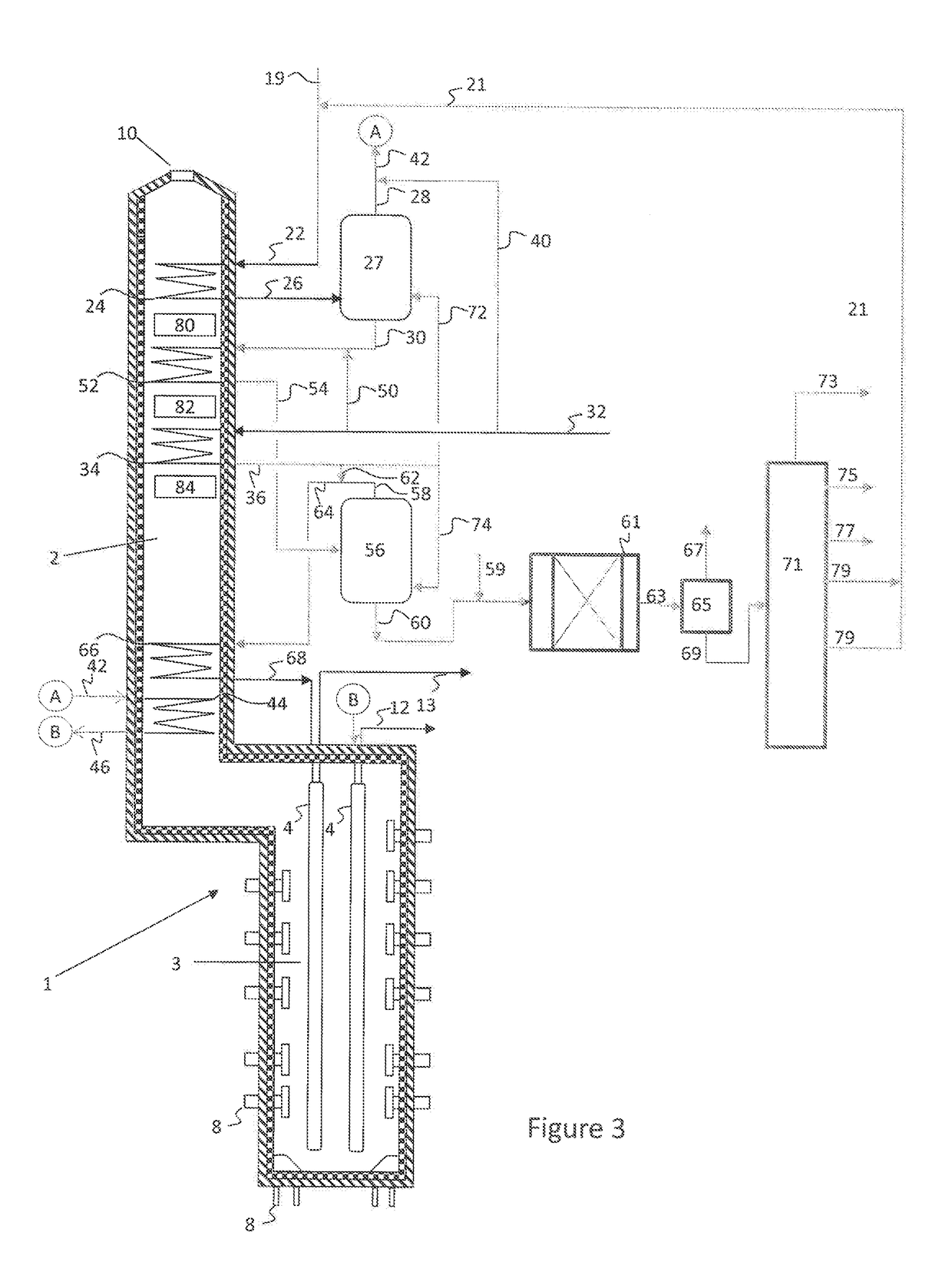
The patent describes a new process for processing whole crudes and other hydrocarbon mixtures containing high boiling coke precursors. This process combines pyrolysis and hydrocracking to reduce coking and fouling, increase yields of desired olefins and aromatics, and decrease the cost and energy associated with separate processing. The process can use one or more hydrocrackers operating at different conditions to optimize chemicals / fuels production. The unconverted oil produced in the hydrocracker can be used as feed in the olefin plant, and the bleed / tar in the hydrocracker can be sold as product to maximize catalyst life. The integrated pyrolysis and hydrocracking process offers a high yield of desired products and valuable fuels without the need for a separate crude separation unit.

Problems solved by technology

While limiting reaction conditions may reduce the fouling tendency, the less severe conditions result in a significant loss in yield.
The products obtained from the crude tower (atmospheric distillation) and from the vacuum tower are used as fuel (gasoline, jet fuel, diesel, etc.) Generally, they do not meet fuel specifications.

Method used


Image

  • Integrated pyrolysis and hydrocracking units for crude oil to chemicals
  • Integrated pyrolysis and hydrocracking units for crude oil to chemicals
  • Integrated pyrolysis and hydrocracking units for crude oil to chemicals

Examples


example 1

rude

[0095]Table 1 shows the calculated yields obtained for crude cracking. All calculations are based on a theoretical model. Assuming run length (even few hours) is not a factor, yields at high severity are shown, although other severities may be used.

[0096]For this Example, a Nigerian light crude is considered. The crude had the properties and distillation curve as shown in Table 1.

TABLE 1Specific Gravity0..79Sulfur, wt %0.04Micro-carbon residue (MCRT), wt %0.67metals, ppm2.1C7 Asphaltene, wt %0.11TBP End Point ° C.Cumulative Yield (wt %)11.715030.220043.526058.134078.245093.657097.7Residue (570° C. +)100

[0097]Simulated pyrolysis yields for cracking the crude, calculated based on a model, are shown in Table 2. Three cases were studied for this example, including: Case 1—whole crude with gas oil product integration; Case 2—whole crude with gas oil integration and a resid hydrocracker, and a reference case, Case 3—pyrolysis of a full range naphtha.

[0098]A naphtha cut (340° C.) are c...

example 2

[0105]Using an Arabian crude, the following material balance is generated.

Material Balance for 11564 KTA Crude feed LPG Free basisCase1A2A3AVacuum Residue Cracking?NoYesYesFuel Oil RecycleNoNoYesCracking SeverityHighHighHighLight Gas668.4668.4668.4Light Naphtha2889.22889.22889.2Heavy Naphtha2390.02390.02390.0Heavy Blend 24052.44052.44052.4Vacuum Residue1564.31564.31564.3Methanol114.3136.3150.7Net Steam Reacted11.913.815.0TOTAL11690.511714.411730.0PRODUCT, KTAHydrogen35.939.942.6Fuel Gas1706.91937.62088.3Ethylene3637.84114.84426.5Propylene from Cracker1572.71822.31985.31,3-Butadiene512.3588.6638.5MTBE314.5375.0414.51-Butene57.967.373.5C9+ Gasoline238.9289.60.0Benzene697.5819.0898.3Toluene527.1575.4607.0Xylene208.6247.8273.5Pyrolysis Gas Oil172.3256.80.0Pyrolysis Fuel Oil435.5570.90.0Residue1564.30.00.0FO Recycle → Vent Gases0.00.032.1FO Recycle → Fuel Oil Residue0.00.0240.0Acid Gases8.39.39.9TOTAL11690.511714.411730.0RECYCLES, KTAC2 Recycle555.1635.9688.6C3 Recycle123.2175.3209.4C4-C...


PUM


Abstract

Integrated pyrolysis and hydrocracking systems and processes for efficiently cracking of hydrocarbon mixtures, such as mixtures including compounds having a normal boiling temperature of greater than 450° C., 500° C., or even greater than 550° C., such as whole crudes for example, are disclosed.

Description

FIELD OF THE DISCLOSURE[0001]Embodiments disclosed herein relate generally to the integrated pyrolysis and hydrocracking of hydrocarbon mixtures, such as whole crudes or other hydrocarbon mixtures, to produce olefins and other chemicals.BACKGROUND[0002]Hydrocarbon mixtures having an end boiling point over 550° C. are generally not processed directly in a pyrolysis reactor to produce olefins, as the reactor cokes fairly rapidly. While limiting reaction conditions may reduce the fouling tendency, the less severe conditions result in a significant loss in yield.[0003]The general consensus in the art is that hydrocarbon mixtures having a wide boiling range and / or hydrocarbons having a high end boiling point require an initial separation of the hydrocarbons into numerous fractions, such as gas / light hydrocarbons, naphtha range hydrocarbons, gas oil, etc., and then cracking each fraction under conditions specific for those fractions, such as in separate cracking furnaces. While the fracti...

Claims


Application Information

Patent Timeline
IPC IPC(8): C10G69/06
CPCC10G69/06C10G2400/20C10G2400/22C10G69/14C10G9/36C10G47/02C10G9/14
Inventor SUNDARAM, KANDASAMY MEENAKSHISTANLEY, STEPHEN J.VENNER, RONALD M.MUKHERJEE, UJJAL K.
Owner LUMMUS TECH LLC
Learn More