Fluorine-containing gas decomposing/removing agent, method for producing same, and fluorine-containing gas removing method and fluorine resource recovery method each using same

Inactive Publication Date: 2020-04-02
CLARIANT CATALYSTS JAPAN
View PDF0 Cites 0 Cited by
  • Summary
  • Abstract
  • Description
  • Claims
  • Application Information

AI Technical Summary

Benefits of technology

[0028]In accordance wit

Problems solved by technology

Among PFCs, perfluorocarbons are considered to be difficult to decompose and remove because they are chemically stable.
As described above, in the above-mentioned conventional method, there is a problem in that the installation of the ancillary facility and the operation thereof have a large load for the hydrofluoric treatment.
This removing agent functions effectively in small volume processing such as laboratory scale, but there is a problem that the decomposition efficiency decreases when scaled up to a reactor of a practical size.
As in this method, a removing agent for decomposing a fluorine-containing gas using water generated by decomposing a hydroxyl group at a reaction temperature has a problem that the removing agent cannot be used any more before the fluorine-containing gas flows in or if the hydroxyl group is lost during the treatment.
That is, if the removing agent before use is exposed to a high temperature due to an error in control of the heater for

Method used


Image

  • Fluorine-containing gas decomposing/removing agent, method for producing same, and fluorine-containing gas removing method and fluorine resource recovery method each using same
  • Fluorine-containing gas decomposing/removing agent, method for producing same, and fluorine-containing gas removing method and fluorine resource recovery method each using same
  • Fluorine-containing gas decomposing/removing agent, method for producing same, and fluorine-containing gas removing method and fluorine resource recovery method each using same

Examples


Example

Example 1

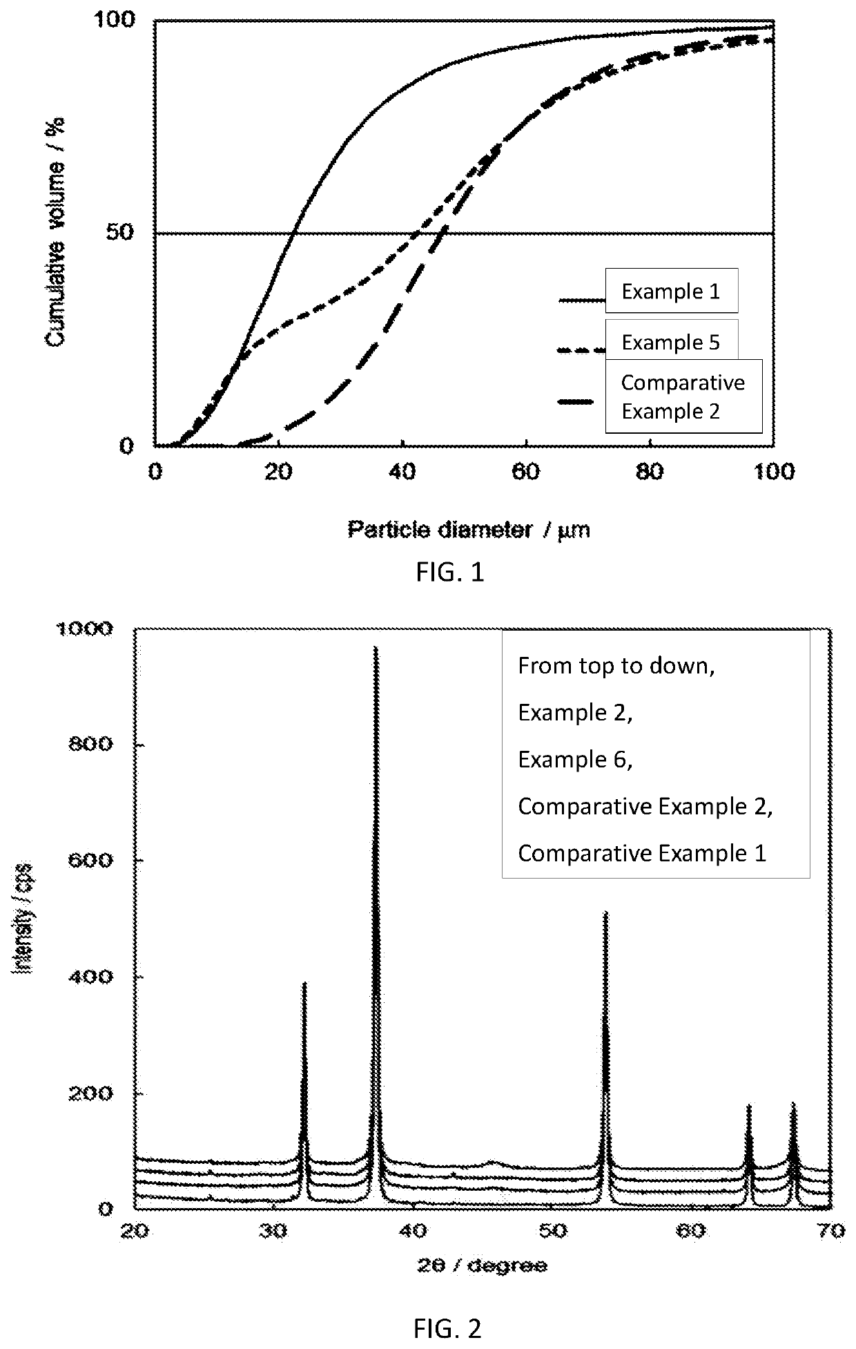
[0107]Preparation of a removing agent sample comprising η alumina and a calcium oxide is as follows. Bayerite (Al(OH)3) powder and a calcium hydroxide powder were weighed so that the molar ratio Al(OH)3:Ca(OH)2 was 5:5, made a kneaded cake (mixture) by mixing in a mix muller (Shinto Kogyo Co., Ltd., Model MSG-0LS) while adding water. Disk Peletor (Non-2 Paudal Co., Ltd., Model F-5) was used to make the kneaded cake in a grain shape of a diameter approximately 2 mm and a length about 6 mm. The obtained grain shape was dried for 5 minutes in a hot air circulation type electric dryer maintained at 120° C. The dried grain shape was calcined in a rotary kiln (an external heat batch type rotary kiln from Takasago Kogyo Co., Ltd.) under a flow of dry air (dew point: −50° C.) of 50 L / min while rotating the retort at 1.5 rpm. The calcining was carried out by holding 700° C. for 30 minutes. The removing agent sample was obtained of Example 1 after cooling to room temperature by opera...

Example

Example 2

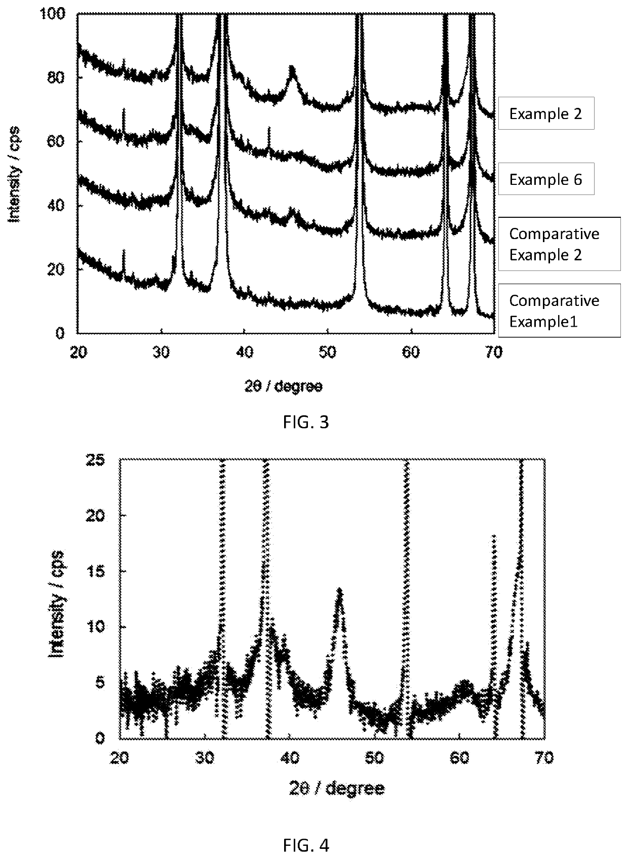
[0109]A removing agent sample of Example 2 of the molar ratio Al(OH)3:Ca(OH)2 of 3:7 was prepared and stored in the same method and conditions of Example (Ex.) 1. The tap density and the CF4 removing agent capacity at the test temperatures of 600° C. are shown in Table 2. The results of analysis on the amount of desorbed ammonia per weight of the removing agent obtained by the ammonia TPD-MS measurement are shown in Table 3.

Example

Example 3

[0110]A removing agent sample of Example 3 of the molar ratio Al(OH)3:Ca(OH)2 of 2:8 was prepared and stored in the same method and conditions of Example 1. The tap density and the CF4 removing agent capacity at the test temperatures of 600° C. are shown in Table 2. The results of analysis on the amount of desorbed ammonia per weight of the removing agent obtained by the ammonia TPD-MS measurement are shown in Table 3.


PUM

PropertyMeasurementUnit
Temperatureaaaaaaaaaa

Abstract

The present invention relates to a fluorine-containing gas removing agent comprising an alumina and an alkali earth metal compound, wherein an ammonia desorption curve obtained by an ammonia TPD-MS method having a mass-to-charge ratio of 15 has a peak in a range lower than 200° C. and has a shoulder in a range of 200° C. or higher.

Description

TECHNICAL FIELD[0001]The present invention relates to a removing agent capable of efficiently decomposing a fluorine-containing gas, in particular, a perfluoro compound (PFC) used for etching in manufacturing a semiconductor or the like or dry cleaning of a CVD apparatus without adding water or oxygen, and fixing fluorine as an alkaline earth metal fluoride in the removing agent, a manufacturing method thereof, a fluorine-containing gas removing method using the same, and a method of recovering a fluorine resource.BACKGROUND OF INVENTION[0002]Fluorocarbons such as CHF3 and PFCs such as CF4, C2F6, C4F8, NF3 and SF6 are used as etching gases in the production of semiconductors and dry cleaning gases in chemical vapor deposition equipment. Since these are gases that promote global warming, they are required to be recovered and reused, and to be discharged after being decomposed into harmless gases having a low global warming potential. Among PFCs, perfluorocarbons are considered to be ...

Claims


Application Information

Patent Timeline
IPC IPC(8): B01D53/70B01D53/14B01J21/04B01D53/81B01D53/86B01J20/04B01J20/08B01J20/28B01J20/30B01J37/04
CPCB01D53/81B01J20/041B01J20/08B01J21/04B01D53/14B01J37/04B01J20/28B01D53/8662B01D53/70B01J20/3014B01D2257/2066B01D2255/2092B01J20/043B01D53/685B01D53/8659B01D2251/402B01D2251/404B01D2257/204B01D2258/0216B01J23/02B01J35/002B01J35/10B01J20/04B01J20/30Y02C20/30B01D53/68B01J20/3007B01J20/3078B01J37/0009B01J37/08
Inventor NAKASHIMA, TADAHITOKIM, HYUN-JOONG
Owner CLARIANT CATALYSTS JAPAN
Why Eureka
Try Eureka