Heat Integration in a Hydrocarbon Processing Facility
- Summary
- Abstract
- Description
- Claims
- Application Information
AI Technical Summary
Benefits of technology
Problems solved by technology
Method used
Image

Examples
example 1
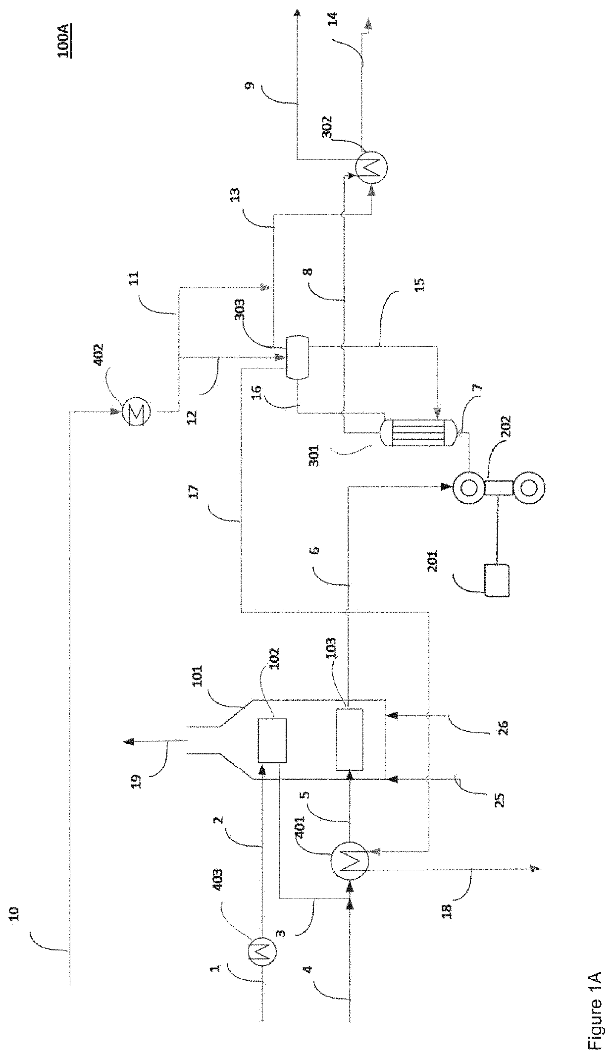
n of a Conventional Plant and a Rotary Reactor Plant (500) Comprising a (Rotary) Cracker Unit 100 Implemented According to a Concept of FIG. 1A
[0202]Table 1 shows the energy- and material balance simulation summary for a conventional plant (Conventional), a rotary reactor plant 500 with a fuel gas operated furnace 101 (Case A. Rotary reactor plant) and a rotary reactor plant 500, where reactor feed preheating (furnace 101) shown in the FIG. 1 has been replaced by electric heaters (Case B. Rotary reactor plant).
TABLE 1A. RotaryB. Rotaryreactor plantreactor plantConventional(500)(500)1Net energy consumption,687.6542.0531.0MWFuel gas export, MW86.2372.3590.5Credit HP steam export100.54.14.1(10 MPa / 100 bar), MWMaterial balanceProductt / ht / ht / hHydrogen, 99.9%2.42.12.1Fuel gas60.140.640.6Ethylene, polymer grade119.1119.1119.1Propylene, polymer grade49.440.740.7Raw C427.820.920.9Pyrolysis gasoline66.756.156.1Pyrolysis fueloil14.02.82.8Naphtha feed, t / h339.4282.1282.1CO2, kg / h144844397780Coo...
example 2
n of a Conventional Plant and a Rotary Reactor Plant (500) Comprising a (Rotary) Cracker Unit 100 Implemented According to a Concept of FIG. 1A, but with the Matching Yields
[0208]Comparative energy- and material balance simulation has been performed for configurations as described in Example 1. The difference relative to the Example 1 is that the operating conditions for the rotary reactor 202 have been selected to essentially match its yields (hereby, ethylene yields) with the (ethylene) yields obtained in the conventional hydrocarbon (naphtha) cracker. This simulation demonstrates the situation, where it is advantageous to maintain the same product distribution when replacing the conventional cracker unit with the rotary reactor cracker unit 100 in the facility 500. The results of simulation are summarized in Table 2.
TABLE 2A. RotaryB. Rotaryreactor plantreactor plantConventional(500)(500)1Net energy consumption,687.6574.2560.3MWFuel Gas export, MW86.2586.1862.2Credit HP steam exp...
example 3
of FIG. 4 Designed for Electric Heating
[0210]In example, configuration of the rotary cracker unit 100 has been implemented according to the layout 100D of FIG. 4. In practice, the mixture of the hydrocarbon containing feedstock and diluent (e.g. naphtha-steam mixture) is preheated in the heat exchanger 401 by the saturated high pressure steam. Superheated process fluid is then heated in the heat recovery unit 302 prior to be routed into the rotary reactor 202. The HRU 302 is implemented in this configuration as a heat exchanger, where the TLE (301) exit gases are used as a heating medium.
[0211]To implement the heating in the facility 500, the medium pressure steam (1.6 MPa / 16 bar) has been imported into the process in this calculation example. Additionally or alternatively, electrical power can be utilized for heating in addition to or instead of the medium pressure steam. By importing the medium pressure steam, electricity consumption can be reduced. Medium pressure steam generatio...
PUM
 Abstract
Description
Claims
Application Information
PatSnap Eureka turns technology decisions into work you can execute. Powered by our Innovation Knowledge Graph, it runs expert workflows across engineering, life sciences, materials and intellectual property. Get your review-ready output in minutes.


