
Sprayed coating, method for manufacturing sprayed coating, sprayed member and spraying material

a technology of sprayed coating and spraying material, which is applied in the direction of superimposed coating process, rare earth metal fluoride, coating, etc., can solve the problems of high production cost, deterioration of process yield, and high production cost of type, and achieve low temperature dependence, good electric characteristics, and small variation of volume resistivities

Inactive Publication Date: 2021-06-24
SHIN ETSU CHEM CO LTD
View PDF2 Cites 0 Cited by
  • Summary
  • Abstract
  • Description
  • Claims
  • Application Information

AI Technical Summary

Benefits of technology

The coating achieves stable electric characteristics with low temperature dependency and reduced particle generation, enhancing the erosion resistance and process yield in semiconductor manufacturing.

Problems solved by technology

Thus, this type has an issue of high production cost.
This type also has an issue of high production cost.
If the size is less than the range, flowability of the particles may become low, resulting a supply tube being clogged with the sprayed material, or the particle introduced in a flame may vaporize, resulting deterioration of process yield (Patent Document 2).
Accordingly, a sprayed coating obtained by thermal spraying with particles having a large average particle size results in many cracks and a large porosity because the splat diameter of the particle is large.
Thus, a dense coating cannot be obtained, and particles generates adversely from the coating in etching process.
These particles may cause deterioration of process yield in manufacturing semiconductor devices.
Thus, the obtained sprayed coating is very dense since splat diameter of the sprayed coating becomes very small.
However, even if the sprayed coating is dense, the yttrium oxide has a problem such that a sprayed coating of yttrium oxide can be progressively halogenated at its surface by chemical reaction of yttrium oxide and halogen series gas plasma, and many yttrium series particles are generated as unfavorable particles source.
To deal with the problem, a sprayed coating obtained from a slurry in which yttrium fluoride or yttrium oxyfluoride spraying particles are dispersed in a medium is proposed, however, a dense sprayed coating that can satisfy current needs has not been formed in this method (Patent Documents 5 and 6).

Method used


Image

  • Sprayed coating, method for manufacturing sprayed coating, sprayed member and spraying material
  • Sprayed coating, method for manufacturing sprayed coating, sprayed member and spraying material

Examples


example 1

[0076]An A5052 aluminum alloy substrate having the surface size of 100 mm square and 5 mm thick was degreased at the surface by acetone, and one surface of the substrate was subjected to roughening treatment with an abrasive corundum. A yttrium oxide sprayed coating of 100 μm thick was formed as a lower layer on the substrate by using an atmospheric plasma spraying apparatus with a yttrium oxide powder (granulated particles) having an average particle size (D50) of 20 μm. As spraying conditions, argon gas and hydrogen gas were used as plasma gases, and output of 30 kW, and spraying distance of 120 mm were applied. The porosity of the lower layer was determined by image analysis method as explained below, and was 2.0%.

[0077]Further, a slurry was prepared such that 30 wt % of yttrium fluoride particles having a BET specific surface area of 0.7 m2 / g and an average particle size (D50) of 3.3 μm was dispersed in ethanol. A yttrium fluoride series sprayed coating of 150 μm thick was forme...

example 2

[0079]An A5052 aluminum alloy substrate having the surface size of 100 mm square and 5 mm thick was degreased at the surface by acetone, and one surface of the substrate was subjected to roughening treatment with an abrasive corundum. An erbium oxide sprayed coating of 100 μm thick was formed as a lower layer on the substrate by using an atmospheric plasma spraying apparatus with an erbium oxide powder (granulated particles) having an average particle size (D50) of 20 μm. As spraying conditions, argon gas and hydrogen gas were used as plasma gases, and output of 30 kW and spraying distance of 120 mm were applied. The porosity of the lower layer was determined by image analysis method as the same in Example 1, and was 3.2%.

[0080]Further, a slurry was prepared such that 30 wt % of erbium fluoride particles having a BET specific surface area of 1.5 m2 / g and an average particle size (D50) of 2.3 μm was dispersed in ethanol. An erbium fluoride series sprayed coating of 100 μm thick was f...

example 3

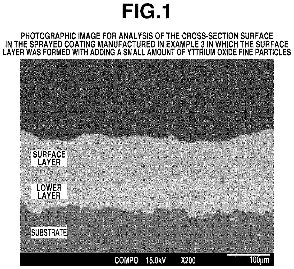
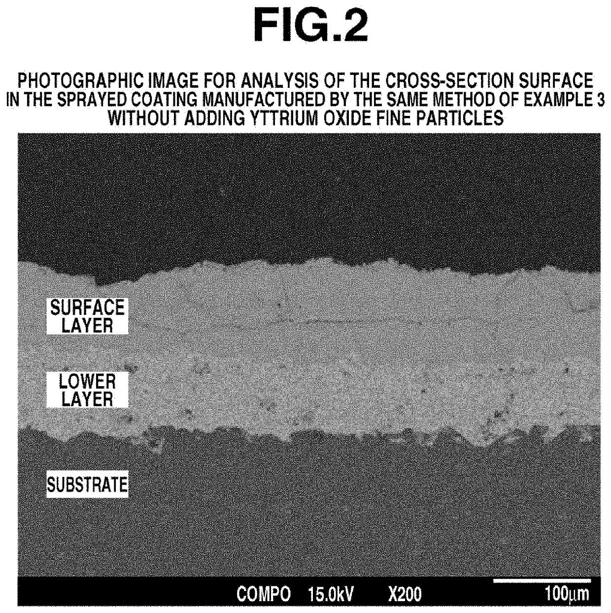
[0081]An A5052 aluminum alloy substrate having the surface size of 100 mm square and 5 mm thick was degreased at the surface by acetone, and one surface of the substrate was subjected to roughening treatment with an abrasive corundum. A yttrium oxide sprayed coating of 100 μm thick was formed as a lower layer on the substrate by using an atmospheric plasma spraying apparatus with a yttrium oxide powder (granulated particles) having an average particle size (D50) of 20 μm. As spraying conditions, argon gas and hydrogen gas were used as plasma gases, and output of 30 kW, and spraying distance of 120 mm were applied. The porosity of the lower layer was determined by image analysis method as the same in Example 1, and was 2.9%.

[0082]Further, a slurry was prepared such that 30 wt % of a mixture of yttrium fluoride particles having a BET specific surface area of 1.0 m2 / g and an average particle size (D50) of 3.7 μm, and yttrium oxide fine particles having a BET specific surface area of 48...


PUM

PropertyMeasurementUnit
volume resistivityaaaaaaaaaa
voltageaaaaaaaaaa
average particle sizeaaaaaaaaaa

Abstract

A sprayed coating having a multilayer structure including a lower layer made a sprayed coating containing a rare earth oxide, and a surface layer made of another sprayed coating containing a rare earth fluoride and / or a rare earth oxyfluoride, the multilayered sprayed coating having a volume resistivity at 23° C. and a volume resistivity at 200° C., the volume resistivity at 23° C. being 1×10⁹ to 1×10¹² Ω·cm, and a temperature index of the volume resistivities defined by the ratio of the volume resistivity at 200° C. to the volume resistivity at 23° C. being 0.1 to 10.

Description

CROSS-REFERENCE TO RELATED APPLICATION[0001]This application is a continuation of U.S. patent application Ser. No. 16 / 539,165 filed on Aug. 13, 2019, which claims priority under 35 U.S.C. § 119(a) on Patent Application No. 2018-152883 filed in Japan on Aug. 15, 2018, the entire disclosure of each of the foregoing is herein incorporated by reference.TECHNICAL FIELD[0002]This invention relates to a sprayed coating suitable for such as an erosion-resistant coating formed on electrostatic chucks, or parts or members in a plasma etching apparatus for a semiconductor manufacturing process. This invention also relates to a method for manufacturing the sprayed coating, a sprayed member formed the sprayed coating, and a spraying material suitably used for forming the sprayed coating.BACKGROUND ART[0003]An electrostatic chuck use for a lower electrode in a semiconductor manufacturing apparatus is generally categorized to two types of a Coulomb force type electrostatic chuck and a Johnson-Rahb...

Claims


Application Information

Patent Timeline
Patent Type & Authority Applications(United States)
IPC IPC(8): C23C4/11C23C4/134
CPCC23C4/11C23C4/134C23C4/04C23C28/042C23C28/00H01L21/6831H01L21/67069H01L21/3065C01F17/265C01P2004/61C01P2006/12C01P2006/14
Inventor IWASAKI, RYOHAMAYA, NORIAKITAKAI, YASUSHINAKANO, HAJIME
Owner SHIN ETSU CHEM CO LTD
Features
  • Generate Ideas
  • Intellectual Property
  • Life Sciences
  • Materials
  • Tech Scout
  • Unparalleled Data Quality
  • Higher Quality Content
  • 60% Fewer Hallucinations
Learn More