
Process for the production of bio-oil and biogas from biomass

a bio-oil and biomass technology, applied in the direction of gaseous fuels, biological sludge treatment, treatment water, etc., can solve the problems of inability to recover biogas from water produced, inability to maintain the operation of the plant, and inability to achieve continuous pilot management. achieve the effect of high biogas efficiency

Pending Publication Date: 2021-09-23
ENI SPA
View PDF2 Cites 2 Cited by
  • Summary
  • Abstract
  • Description
  • Claims
  • Application Information

AI Technical Summary

Benefits of technology

The patent text describes a method for efficiently producing advanced biofuels from organic waste and scrap, specifically through the use of an anaerobic digestion process. The method involves multiple stages and conditions to maximize the conversion of organic matter to biogas and bio-oil, which can then be further utilized for energy production. The technical effects of the invention include improved COD removal and high conversion of organic matter to advanced biofuel with high energy efficiency.

Problems solved by technology

Said plant has had numerous shutdowns and has never reached full operational capacity.
In a recent presentation at a conference (https: / / bioenergy.conferenceseries.com / abstract / 2017 / catlig-catalytic-hydrothermal-liquefaction-process-from-pilot-scale-to-demo-scale—7th International Congress on Biofuels and Bioenergy Oct. 2-4, 2017 Toronto, Canada), it is explained that continuous pilot management has been limited by the fact that the process fluids produced scale, clogging and flows of particles.
In this process, the water produced is not treated to recover biogas.
The solvent system is, however, a costly one to manage.
The existing literature outlines how water from OFMSW liquefaction can actually cause a toxicity problem related to some of the chemical compounds present, such as methyl-hydroxy-pyridines, potentially biodegradable, but characterised by high toxicity to methanogenic micro-organisms (micro-organisms capable of activating the formation of biogas).
If liquefaction is carried out under supercritical conditions, the energy available in the biomass is not sufficient and therefore it is necessary to use an external energy source.
The disadvantage of the proposed scheme is that, in addition to hydrothermal liquefaction conditions close to supercritical conditions, water treatment is also carried out under particularly severe conditions and is therefore extremely costly in terms of investment, building materials and energy consumption.
This reaction has been studied for years but the process has not yet found industrial applications, mainly because of the prohibitive costs associated with the scale-up of equipment to be managed at high pressure (greater than or equal to 200 bar).
The liquefaction of organic biomass under supercritical conditions, which typically provide for a temperature range between 370° C. and 400° C. and pressure ranging from 220 bar to 250 bar, involves investment costs and energy costs (due to the need to supply energy from an external source) that are very significant and as such slow down and postpone industrial performance thereof.
Biomass liquefaction in subcritical conditions co-produces bio-oil considered as “advanced biofuel”, and an aqueous phase with low biodegradability under standard anaerobic digestion conditions resulting in low biogas production.
This leads to the need to send the liquefaction waters still loaded with COD to large water treatment plants, with increased disposal costs.
The problems that can be found in the anaerobic digestion of liquefaction waters obtained under subcritical conditions are various.
In addition, the presence is observed of compounds that are difficult to biodegrade anaerobically or specific toxic compounds and metabolic products derived from digestion itself: compounds that have molecular structures that are not similar to those of natural substances, which are decomposed with difficulty, slowly (through non-dedicated co-metabolism) or not at all.

Method used


Image

  • Process for the production of bio-oil and biogas from biomass
  • Process for the production of bio-oil and biogas from biomass
  • Process for the production of bio-oil and biogas from biomass

Examples


example 2

Anaerobic Digestion of Liquefaction Waters from OFMSW (Batch Tests in 20 ml Syringe Reactors)

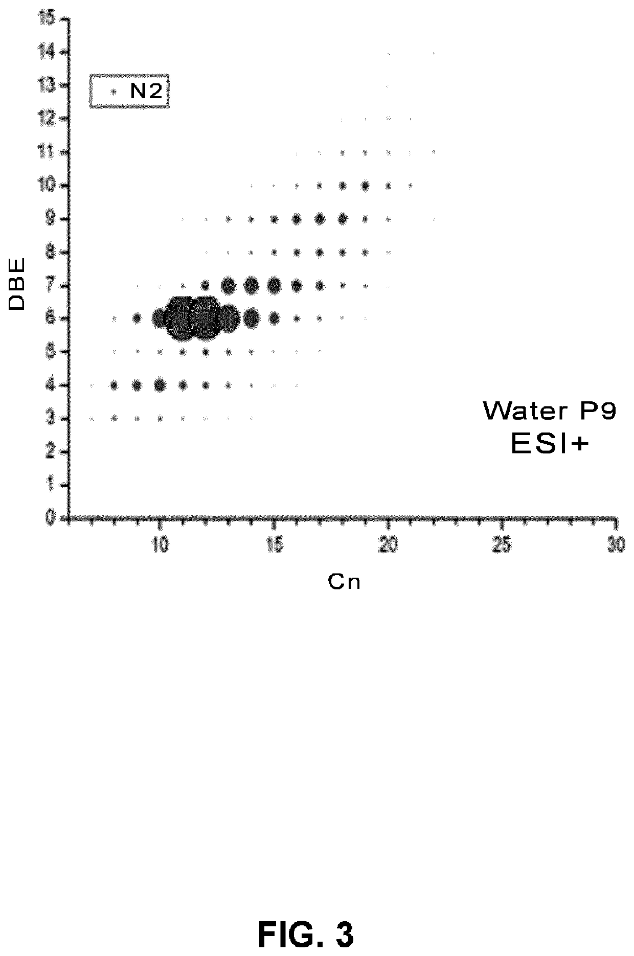
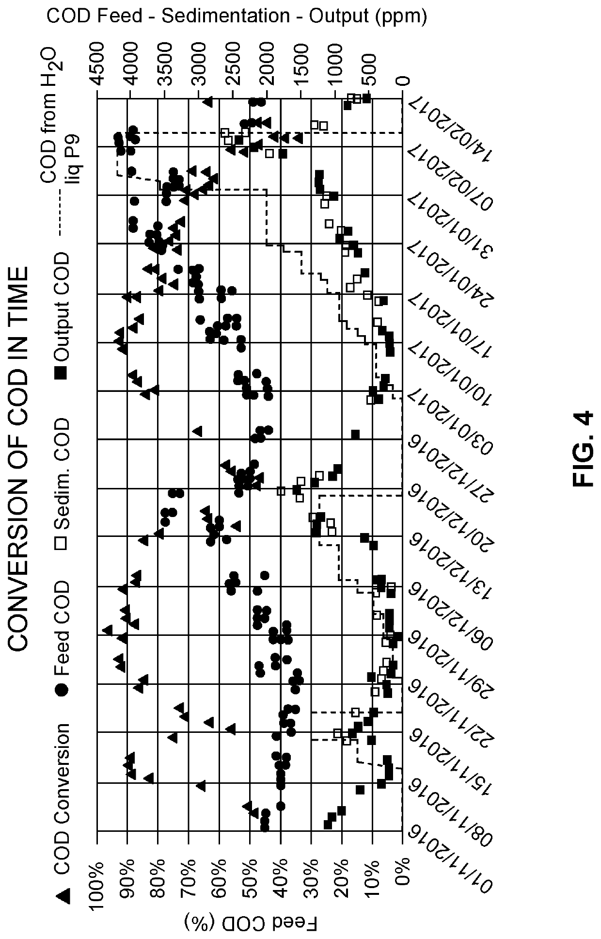
[0162]Anaerobic digestion tests were carried out on the same liquefaction waters described in Example 1 (water P9) in 20 ml syringe reactors, with measurements of COD conversion, biogas production, and generation of anaerobic digestion intermediates, in particular VFAs.

[0163]The methods of performing the tests are described below and shown in FIG. 6.

[0164]1) Remove the plunger, close the tip of the syringe with the rubber cap, add the anaerobic mud (inoculum) and the liquefaction water for a total of 20 ml.

[0165]2) Close the syringe with the plunger.

[0166]3) Turn over the syringe and let the contents settle on the bottom.

[0167]4) Slowly release the internal pressure by removing the cap, expel the air.

[0168]5) Close the syringe with the cap.

[0169]6) Put the syringe in the stove conditioned to the reaction temperature 40 or 60° C.

[0170]7) Determine the biogas produced every 24 hours, reading t...

example 3

Anaerobic Digestion of the Liquefaction Waters from OFMSW (Continuous Testing in 80 ml Reactors)

[0178]A continuous two-stage anaerobic digestion test was carried out on the liquefaction waters described in Example 1 (water P9) in reactors each with a volume of 80 ml. The reactor temperatures are maintained at 60 and 40° C. by electric heating. The aqueous phases are fed to the first and second reactors by means of peristaltic pumps. An external recirculation from the second to the first reactor with peristaltic pump is provided. The gas and liquid leaving the second reactor are sampled and sent for analysis.

[0179]The methods of performing the test are described with the aid of FIG. 10 and the results are shown in FIG. 11.

[0180]The reactors are initially started up with 30 ml of active sludge inoculum and 50 ml of water and glucose to a COD of 21400 mg / kg. The same solution is continuously fed to the 1st reactor at 5 ml / day, corresponding to an HRT (hydraulic retention time) of 16 da...


PUM


Abstract

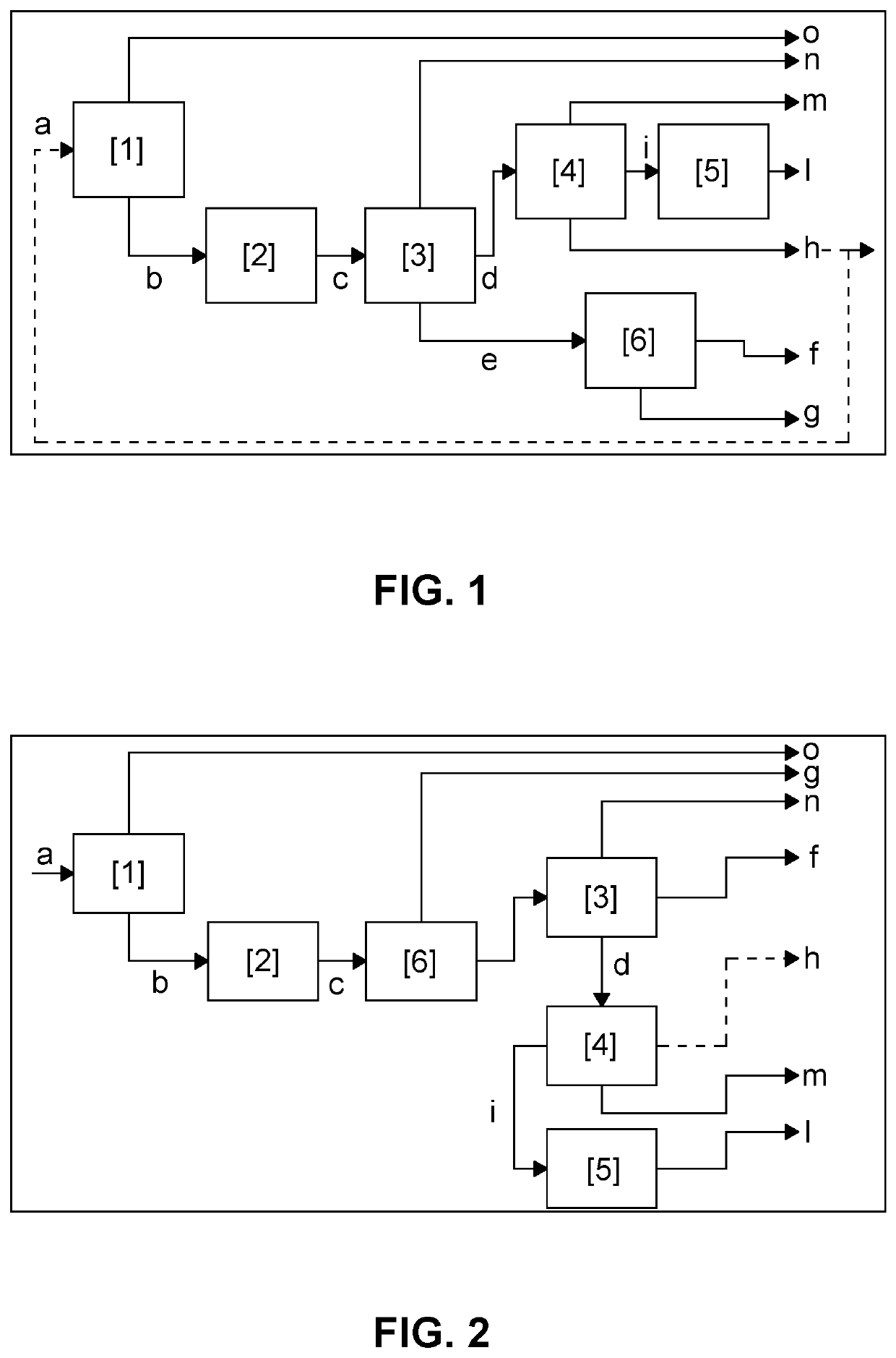
There is a process for the production of a liquid fuel and of a gaseous fuel from biomass. The biomass is sent to a pre-treatment section to form a homogeneous phase that can be moved and / or pumped, wherein inert parts are separated from the biomass and the biomass shredded and / or ground to reduce its size. The homogeneous phase obtained is then subjected to subcritical hydrothermal liquefaction at a temperature between 240° C. and 310° C. to form a liquefied phase. The liquefied phase is separated. After separation, the process continues in two alternative and mutually exclusive modes. In the first mode, the first aqueous phase is subjected to an anaerobic reaction with multiple stages producing biogas; the oily phase is separated into a bio-oil and a solid residue. In the second mode, the separate mixed phase is separated by density or dynamics forming a first aqueous phase, bio-oil and a gaseous phase. The first aqueous phase is subjected to a multiple-stage anaerobic reaction from which biogas, a muddy current and a second aqueous phase are produced.

Description

CROSS-REFERENCE TO A RELATED APPLICATION[0001]The present application claims benefit from PCT / EP2019 / 070707, filed Jul. 31, 2019, which claim priority based on Italy Patent Appl. No. 102018000007569, filed Jul. 27, 2018. The contents of the foregoing applications are incorporated herein by reference in their entireties.BACKGROUND OF THE DISCLOSURE1. Field of the Disclosure[0002]The present disclosure relates to a process for the production of liquid fuel, preferably bio-oil, and of a gaseous fuel, preferably biogas, from biomass, with the aim of obtaining a high conversion thereof to advanced biofuel combined with high energy efficiency.2. Description of the Related Art[0003]The review “M. Deniel et al Renewable and Sustainable Energy Reviews 54 (2016) 1632-1652” describes the recovery of food residues by liquefaction. Liquefaction under subcritical conditions is well studied, and an optimal temperature of around 300° C. is defined for most substrates.[0004]The first liquefaction pl...

Claims


Application Information

Patent Timeline
IPC IPC(8): C10L9/08C10L3/08C10G1/06C02F3/02C02F11/04
CPCC10L9/086C10L3/08C10G1/065C02F3/02C02F2103/36C10G2300/1011C10G2300/4006C10G2300/4012C10G2300/805C02F11/04C10L9/08Y02E50/30C10L2290/26C10L2290/547C02F3/30
Inventor MIGLIO, ROBERTAPAGLINO, ROBERTOTORRI, CHRISTIANKIWAN, ALISARFABBRI, DANIELE
Owner ENI SPA
Learn More