Carbon artifacts and compositions and processes for their manufacture

a technology of carbon artifacts and compositions, applied in the field of carbon artifacts, can solve the problems of inability to evaporate carbon in the conventional sense, and difficulty in achieving the effect of high carbon content, saving evaporation requirements, and simple processing

Inactive Publication Date: 2000-01-11
MOTORCARBON
View PDF4 Cites 45 Cited by
  • Summary
  • Abstract
  • Description
  • Claims
  • Application Information

AI Technical Summary

Benefits of technology

Pitch: The preferred starting material for the present invention is Ashland Petroleum Co. A240 pitch because of its commercial availability, high carbon content and well-known properties, other grades can be substituted. Where commercially available, A80 pitch will be particularly useful because it carbon content is about 80 percent or above, thus saving evaporation requirements. Even more preferably, powder will be prepared from Aerocarb "80" pitch, which is produced under license of the Ashland synthesis technology. Several higher char yield variants of the A-80 can also be prepared by thermal treatment of the as-received material. Such treatments will also induce mesophase formation, which may then be evaluated for suitability for the intended purpose of the finished artifact. Aerocarb 80 is one member of a family of pitches derived by means of a patented controlled evaporation of Ashland's commodity pitch, A-240. Aerocarb 80, while still isotropic, is on the verge of becoming mesophase, and has a density of 1.26 g/cm3, a Tg of 224.degree. C. and a softening point of 258.degree. C. Pr

Problems solved by technology

Yet carbon can neither be melted nor sintered in the conventional sense, and thus net shape processing is problematic.
But the conversion of the pitches to solid carbon requires the diffusion of large amounts of hydrogen and alkanes from the interior of a solid body.
Although this approach significantly increases the effective char yield, the outgassing process produces substantial shrinkage and can take months in a thick section, if shrinkage cracking is to be avoided.
Since the fibers are discontinuous, they are mobile and thus do not inhibit local matrix

Method used


Image

  • Carbon artifacts and compositions and processes for their manufacture
  • Carbon artifacts and compositions and processes for their manufacture
  • Carbon artifacts and compositions and processes for their manufacture

Examples


example 2

(Preparation of the carbon artifacts of the invention)

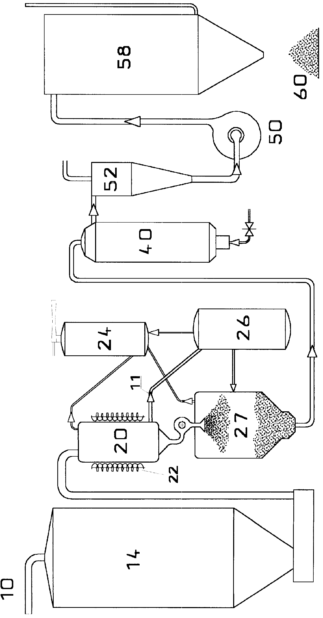
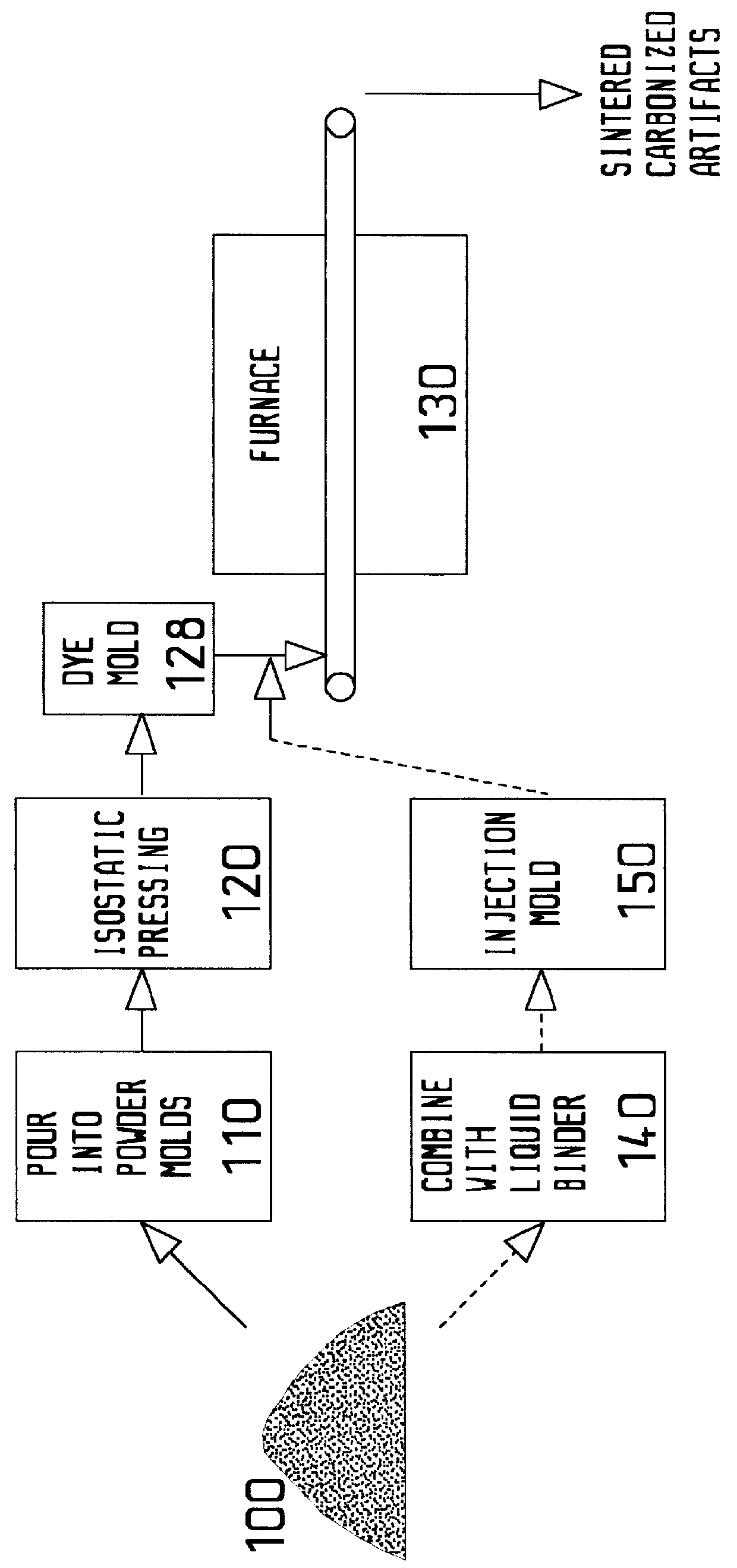
Referring now to FIG. 2, powder 100 such as that produced in Example 1 is poured into individual molds 110. The filled molds are then subjected to isostatic pressing in press 120 which uses a rubber bladder that surrounds the mold and exerts equal pressure in all directions on the powder 100 to be molded. The pressing continues for 20 minutes at a pressure of about 1500 atmospheres. The molds are then processed in demolding step 128, where the molded shapes are released from the molds. These shapes move through multizone moving hearth furnace 130 operating at a start temperature of degrees F. (350 degrees C.) for sintering and finishing carbonizing at 2000 to 2400 degrees F. (1100-1300 degrees C.) for a residence time of about 2 hours to sinter and carbonize the shapes and produce the finished near net shape carbon artifact.

example 3

(Preparation of the carbon artifacts of the invention using binders)

Still referring to FIG. 2 and the other steps discussed in Example 2, in place of (or in combination with) isostatic pressing, the powder 100 can be combined with a binder e.g. phenolic resin, bis oxoazoline, A80 pitch, or the like and injected into injection mold 150 to produce a shape which is demolded in step 128 and sintered and carbonized in furnace 130, as described above.

example 4

(Use in an i-c engine)

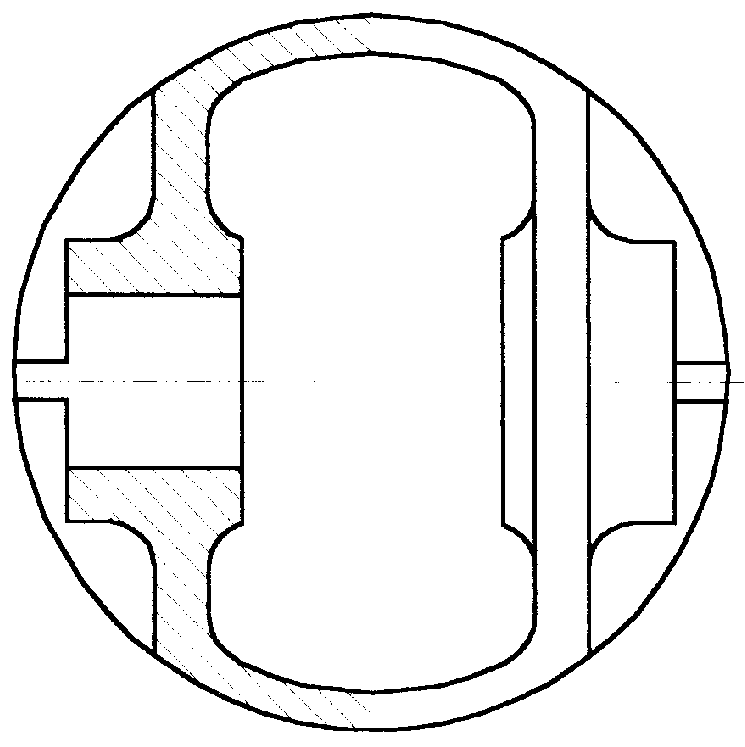
When a piston for a 2-cycle lawnmower engine is manufactured according to Examples 1 and 2, with only light machining, it is installed in the engine where it operates with substantially reduced blow-by of oil into the engine exhaust, due to the dimensional stability of the carbon piston.


PUM

PropertyMeasurementUnit
Lengthaaaaaaaaaa
Fractionaaaaaaaaaa
Fractionaaaaaaaaaa

Abstract

Producing of near net shape carbon (optionally carbon-carbon composite) pistons and other artifacts by sintering (with or without carbon fibers, preferably pitch-based carbon fibers and most preferably blends of vapor grown carbon fibers(VGCF)) homogeneous powders derived from petroleum pitch. The powders preferably exhibit properties equal to or exceeding those of POCO AXF-5Q. Preferred specific technical steps are substantially as follows: 1. Individually prepare, by evaporation, heat treating and/or oxidizing of carbon-containing pitches, followed by oxidizing, comminuting and/or spray drying, to produce sinterable pitch powders (and optionally create uniform dryblends of pitch powder with various fractions of vapor-grown or other carbon fiber.) 2. Produce near net shape carbon-carbon artifacts, such as cup shapes which are convertible to internal-combustion (i-c) pistons with minimal machining, by pressing or injecting into molds, then sintering and carbonizing. Both uniaxially (e.g. injection molded) and isostatically compacted powder blends, can be employed. Related apparatus, compositions and artifacts are also taught.

Description

I. Field of the InventionThe present invention relates to the general field of manufacture of artifacts, most preferably engine pistons, from carbon and related processes and compositions.II. Description of the Prior ArtThe following references are understood to be relevant to the field of the invention:1 P. Greiner, German Patent DE 3605918, Feb. 25, 1986.2 P. Greiner, German Patent DE 3638533, Nov. 11, 1986.3 P. Greiner, and H. Pflueger, "Piston Engine", European Patent 0258330B1, May 5, 1992.6 A. H. Taylor, "Lightweight Piston", U.S. Pat. No. 4,683,809, August 1987.7 A. H. Taylor, "Composite Piston", U.S. Pat. No. 4,736,676, April 1988.8 A. H. Taylor, "Lightweight Piston Architecture", U.S. Pat. No. 4,909,133, March 1990.9 K. H. Jones, "Carbon--Carbon Piston", TOPS Exhibit Y-630 available at http. / / tag-www.larc.nasa.gov / tops / tops.html, Sep. 20, 1995.10 A. H. Taylor and P. O. Ransone, "Advanced Carbon--Carbon Piston Development Program--a Status Report", Proceedings of the 13th Co...

Claims


Application Information

Patent Timeline
IPC IPC(8): C04B35/528F02F7/00F02F3/00
CPCC04B35/528F02F3/00F02F7/0085Y10T428/30F05C2203/0808F05C2251/042F05C2253/16F05C2201/021
Inventor HAGER, JOSEPH W.NEWMAN, JOHN W.JOHANNES, NICHOLASTURRILL, FRANK H.
Owner MOTORCARBON
Why Eureka
Try Eureka