Method of construction for density screening outer transport walls

a technology of outer transport walls and construction methods, which is applied in the field of construction methods for density screening outer transport walls, can solve the problems of centrifuge outer walls, high cost of actual materials and equipment, and extremely hostile environment for any chosen construction material, and achieves extremely uniform weight and density characteristics, and low tolerance for weight or density imbalances

Inactive Publication Date: 2000-03-07
BERKELEY F FULLER
View PDF9 Cites 61 Cited by
  • Summary
  • Abstract
  • Description
  • Claims
  • Application Information

AI Technical Summary

Benefits of technology

When the inventors committed their researches to the re-thinking of the basic material, or materials, used to fabricate centrifuge outer walls, they also became freed up to consider using multiple materials, in a hybrid sandwich, with each layer of material being chosen to do a specific indicated job in the strongest, least expensive way possible.
The researchers chose to emulate or model the sequential trajectory of heavy particles being thrown from the core of a rotating centrifuge, out to and as it developed, through the outer wall of a centrifuge. This intellectual process of following a hypothetical thrown particle, along its journey from the inside of the outer wall to the outside, and assessing the materiel requirements of an ideal centrifuge outer wall at each point of this trajectory, led to the following sequential or layered analysis of the ideal characteristics for each point or layer of this journey.
The primary, explicit job of a centrifuge is to throw heavies outward, thus sorting them away from the lighter fluid flow of the device's center core. The ejecting heavies, the densest and often most abrasive materials in a given fluid flow, thus constantly bombard the innermost or facing surface of the outer wall of a centrifuge. The inventors' review of old and new manufacturing materials and of their related fabricating processes, as available in the late 1990's, led through the manufacturing taxonomy to "non-shaping", and then to "surface finishing" and then to "surface coating" (see FIG. 3, a reproduction of page 8, Dodd, Allen & Alting, op.cit.).
In-depth review of many different types of "high-tech" surface coatings revealed how, among many ...

Problems solved by technology

In manufacturing, the actual materials and equipment used are costly, but these costs are substantially determined by those responsible for product design before manufacturing even begins.
First, regarding wear surfaces, centrifuge interiors in general and particularly the interior surface of the outer wall of a centrifuge, are an extremely punishing and hostile environment for any chosen construction materials.
To put this yet another way, a centrifuge outer wall of a given outer diameter ("x" inches) operating at its maximum burst strength RPM's will likely experience structural failure if that centrifuge's rotational speed is further increased.
And, conversely, a given centrifuge operating at its maximum outer wall burst strength at a fixed RPM will also likely fail at that RPM if its design diameter is further increased.
The well-documented strength ceilings for steel, titanium and alloy metal used in centrifuge outer walls, and the well-known ratios of rotational speed/centrifugal force times diameter which are governed by those limitations, have created widely accepted limitations for the use of centrifuges.
What appears not to be possible using the decades-old metal based methods of construction and assumptions inherent to all conventional centrifuges is the processing of comparatively large volumes of fluid at centrifugal forces well above approximately 2,500 to 3,000 gravities.
This cannot presently be done because metals cannot provide sufficient hoop or bursting strength to contain the heavier, high volumes, in large diameters, at higher gravities.
Many of today's most pressing environmental problems present very high processing volumes combined with extremely fine, light (and often very dangerous, i.e., cryptosporidium cysts in water supply) particles requiring separation.
However the very high initial cost of and extensive ongoing maintenance required by each of these centrifuges has so far inhibited their use in large arrays of many of such devices, as would be required, for example, to continuously treat all the drinking water for a large metropolitan area.
In addition, more and more long-term health disadvantages of the use of chemicals in water, both individually and from the side-effects of their combinations, are coming to light.
These widespread and intractable disadvantages further underscore the desirability of cost, strength, volume and operating breakthroughs in centrifuge design generally, as dictated by centrifuge outer wall design specifically.
Those disk centrifuges which use stacked disk cores to amplify gravitational separation can separate quite small particles from fluids, in industrial size quantities, due to that amplification technique allowing the use of rotational forces below 3,000 gravities; however, such extremely complex, and maintenance-intensive devices cost many hundreds of thousands of dollars each.
Again, they have not been adopted for large scale fluid separation such as water treatment, most likely because they are not cost-effective for such mass use.
Finally, commercial decanting centrifuges' upper centrifugal limits in the 2,500 gravity range, lacking the amplifier effect of stacked disks, cannot remove particles below approximately 3 to 5 microns.
And, large volume Decanters are also extremely expensive, approaching one mill...

Method used


Image

  • Method of construction for density screening outer transport walls
  • Method of construction for density screening outer transport walls
  • Method of construction for density screening outer transport walls

Examples


first embodiment -

First Embodiment--Monolithic Casting

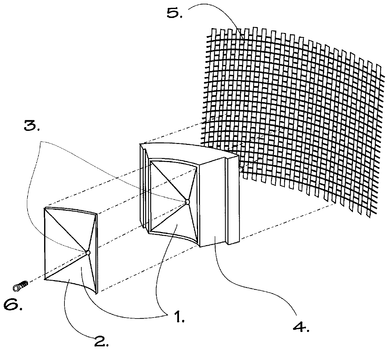
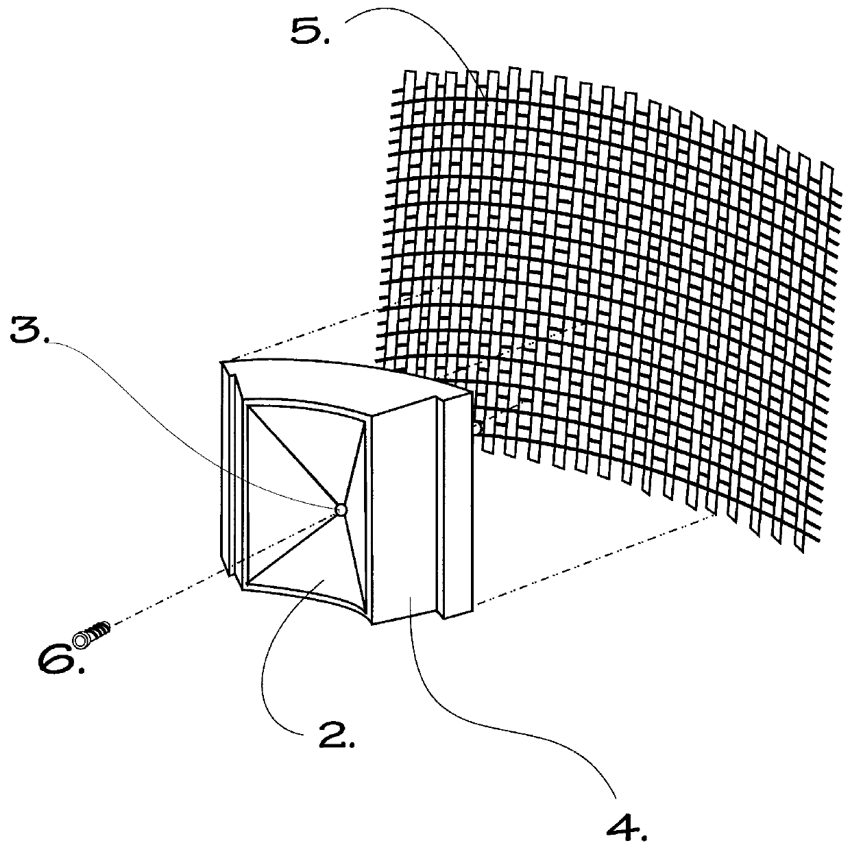
As a significant part of the work done to develop the Density Screening outer wall transport method, the inventors have extensively reviewed late 20.sup.th century material science from manufacturing areas entirely outside of centrifugal devices. This review of so-called new materials has led to another key feature of the Density Screening method, which is to combine in a hybrid or sandwich construction manner, three different material technologies, each ideally suited to solving selected challenges in centrifuge design and performance. FIGS. 1 and 2 illustrate the deceptively simple appearing outcome of this re-thinking.

Reading FIGS. 1 and 2 from left to right, the sequence of materials in the optimum hybrid or sandwich construction of one cut-away, pyramidal void section of a Density Screening outer wall is presented as each would be sequentially encountered by a heavy particle being thrown via centrifugal force, outwards from the spinning colum...

second embodiment

--Assembly of Sub-Castings

The inventors have thoroughly developed a second technique for fabricating the all-important compression load-transferring layer for Density Screening outer transport walls. This technique is to produce multiple castings and then assemble them around the centrifuge core. As with the monolithic castings, wear surface inserts protect the leading, or bombardment side of each void casting area.

Two different schemes have been developed for assembling multiple compression load-transfer castings into completed outer walls, horizontal, and vertical. Horizontal castings (FIGS. 11 and 12) offer much of the torsional rigidity of the monolithic casting means, but each of the horizontal castings is simpler to lay out, having fewer multiple intricate elements, and thus may be less expensive.

A second advantage of stacking multiple horizontal castings is the option this means affords for incorporating different slope angles and other void geometry variations from horizonta...


PUM

PropertyMeasurementUnit
Wear resistanceaaaaaaaaaa
Densityaaaaaaaaaa
Strengthaaaaaaaaaa

Abstract

A method for combining three different means of constructing the concentric layers of the outer collecting wall for industrial size centrifuges, whereby treating the inward-facing elements of easily cast or stamped materials using processes such as Physical Vapor Deposition, Chemical Vapor Deposition or metal plating, transforms them into an innermost member with superior hardness and durability, and whereby said wear surface member or deposited layer is physically supported by a middle composite layer made up of one or more investment castings designed to optimally transfer centrifugally-induced compression loads from the innermost wear surface toward the outer surface of the composite wall, such castings being of ceramic, metals or other materials, and whereby the outer surface of said composite wall is comprised of a filament-wound hoop strength reinforcement layer, using aramid, graphic, carbon or such fibers mixed and embedded in resin, such that all highly desirable characteristics for a centrifuge outer, heavies-collecting wall are provided, including interior hardness and wear abrasion, incompressibility and intrinsic dynamic balance, and substantially higher hoop or bursting strength, than can be attained through any metal-crafted centrifuge outer wall, and, model for model, for substantially lower design and fabrication costs.

Description

BACKGROUND--FIELD OF INVENTIONThe pertinent field of the invention is the "imperforate bowl," related to prior art under "fluid separation," especially "Disk Centrifuges," "Nozzle Centrifuges," and "Split Bowl Centrifuges"BACKGROUND--DESCRIPTION OF PRIOR ARTWithin the scope of this application, prior art is taken to mean conventional methods of construction for the outer walls of centrifuges. One such method for such design, fabrication and assembly predominates for all major types or classes of imperforate bowl centrifugal devices, including notably: (1) those used to separate small volumes of materials, such as Test Tube, Tubal, Preparatory and Zonal Centrifuges; and (2) those used to process industrial volumes of materials, including Decanting Centrifuges, and Disc Centrifuges. Disk type imperforate bowl devices further break down into Manual Discharge, Intermittent Discharge (Split Bowl and Valve Nozzle), and Continuous Discharge (Open Nozzle) models.To put the conventional meth...

Claims


Application Information

Patent Timeline
IPC IPC(8): B04B1/10B04B7/08B04B1/00B04B7/00
CPCB04B1/00B04B1/10B04B7/08B04B7/085Y10T29/49982Y10T29/49984Y10T156/1378Y10T29/4998B04B2005/0464
Inventor KIRKER, CURTISFULLER, BERKELEY F.
Owner BERKELEY F FULLER
Why Eureka
Try Eureka