Method for making an optical recording medium

a recording medium and optical recording technology, applied in the field of phase change optical recording medium, can solve the problems of inconvenient outer edge reflectance, inconsistent reflectance, and decrease in the erasing rate of the distance between the record marks, and achieve the effects of preventing the oxidation of the recording and the reflective layer in their edge portion, reducing the number of overwritable operations, and reducing the erasing ra

Inactive Publication Date: 2000-04-18
TDK CORPARATION
View PDF9 Cites 28 Cited by
  • Summary
  • Abstract
  • Description
  • Claims
  • Application Information

AI Technical Summary

Benefits of technology

exposure period is too short, the effects of the invention are not satisfactorily realized. When the exposure treatment is carried out in an atmosphere containing moisture as in the case of open air, an exposure for excessively long period invites moisture absorption by the substrate, and when the recording layer and reflective layer are subsequently formed on the lower dielectric layer by sputtering, the edge portions of the recording and reflective layers (inner and outer edge portions in the case of an optical recording disc) are inconsistently oxidized to result in an inconsistent reflectance. Occurrence of such oxidation can be visually confirmed as discoloration in the edge portions. In the case of an optical recording disc, recording area normally extends to the vicinity of the outer edge portion, and an inconsistent reflectance in the outer edge portion is inconvenient. In order to prevent such inconsistent oxidation, the step of the exposure treatment is preferably carried out in an atmosphere at a relative humidity of up to 20%. Alternatively, when the exposure treatment is carried out in a moist atmosphere as in the case of open air, the exposure treatment is preferably conducted for a period shorter than 3 hours to prevent the oxidation of the recording and the reflective layers in their edge portions.
According to the second aspect of the present invention, the period of the exposure treatment can be markedly shortened in the embodiment wherein the heat treatment is independently conducted after the exposure treatment, and in such embodiment, even an instantaneous exposure to an oxidative atmosphere such as air may be sufficient. Occurrence of the edge oxidation of the recording and the reflective layers as mentioned above is thus prevented. Preferably, the exposure treatment in such case is effected at least for 1 second, and more preferably, for at least 10 seconds, and exposure for more than 1 minute is generally unnecessary.
In the heat treatment according to the second aspect of the present invention, the lowe

Problems solved by technology

It is assumed that the increase in jitter and the drop in C/N upon repeated overwriting is caused by such mechanism which in turn invites decrease in erasing rate and unstabilization of the distance between the record marks.
When the exposure treatment is carried out in an atmosphere containing moisture as in the case of open air, an exposure for excessively long period invites moisture absorption by the substrate, and when the recording layer and reflective layer are subsequently formed on the lower dielectric layer by sputtering, the edge portions of the recording and reflective layers (inner and outer edge portions in the case of an optical recording disc) are inconsistently oxidized to result in an inconsistent reflectance.
In the case of an optical recording disc, recording area normally extends to the vicinity of the outer edge portion, and an inconsistent reflectance in the outer edge portion is inconvenient.
When the heat treatment temperature is too low, the number of overwritable operations is not sufficiently increased, and the exposure treatment has to be effected for a longer period to adversely affect the productivity.
When the heat treatment temperature is too high, the substrate, if it is made of a resinous material, may undergo undesirable deformation.
When the dielectric layer is prepared from zinc sulfide alone, the dielectric layer is excessively hard, and heat impacts in the overwriting operations may result in delamination of the dielectric layer, leading to poor rewriting durability.
When the content of the zinc sulfide is insufficient, heat conductivity will be too high and refractive index will be too low, and high C/N can not be obtained.
On the other hand, an excessively high zinc sulfide content results in poor rewriting durability.
If the value of b is too small, the content of tellurium would be too much and record marks are more likely to crystallize when the medium is stored at elevated temperature with a loss of reliability.

Method used


Image

  • Method for making an optical recording medium

Examples


example 1 (

According to First Aspect of the Invention)

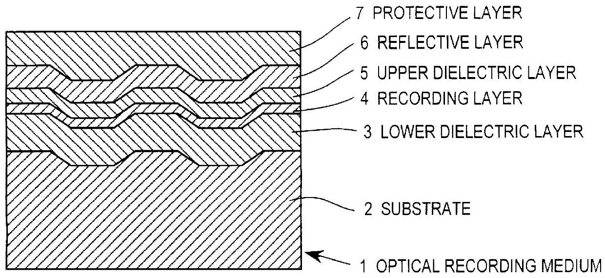
An optical recording disc as shown in FIG. 1 was prepared by injection molding polycarbonate into a disc shaped substrate 2 having a diameter of 120 mm and a thickness of 0.6 mm. A groove was formed in one major surface of the substrate simultaneous with the injection molding. The groove had a width of 0.74 .mu.m, a depth of 650 .ANG., and a pitch of 1.48 .mu.m. On the grooved surface of the substrate, there were formed a lower dielectric layer 3, a recording layer 4, an upper dielectric layer 5, a reflective layer 6, and a protective layer 7.

The lower dielectric layer 3 was formed by sputtering a target of ZnS (80% by mole) and SiO, (20% by mole). The lower dielectric layer 3 had a thickness of 1,100 .ANG..

After forming the lower dielectric layer 3, the disc was taken out of the sputtering apparatus to carry out the exposure treatment, in which the lower dielectric layer 3 was exposed to an atmosphere at a temperature of 23.degree. C. and ...

example 2 (

According to Second Aspect of the Invention)

The procedure of Example 1 was repeated except that a heat treatment was conducted after the exposure treatment to prepare the optical recording disc samples. The exposure treatment was carried out in an atmosphere the same as Example 1 for the period shown in Table 2, and the heat treatment was carried out in nitrogen atmosphere (relative humidity, 10%) at 70.degree. C. for the period shown in Table 2.

The resulting samples were evaluated by repeating the procedure of Example 1. The results are shown in Table 2.

The maximum number of overwritable operations of the samples shown in Table 2 is the same as those of the samples shown in Table 1. In the samples of the Table 1, however, an exposure of 1 week was necessary to achieve 100,000 overwritable operations, and such long exposure invited an undesirable large fluctuation of reflectance. In contrast, in the samples of Table 2, the number of overwritable operations drastically increased by c...


PUM


Abstract

A method for preparing an optical recording medium of phase change type is provided. This recording medium comprises a substrate, a recording layer, and a lower and an upper dielectric layers provided in direct contact with the recording layer. In this method, a step of an exposure treatment wherein the surface of the lower dielectric layer is exposed to an oxidative atmosphere is conducted after forming the lower dielectric layer on the substrate and before forming the recording layer on the lower dielectric layer. A step of a heat treatment wherein said lower dielectric layer is heat treated may be carried out in addition to the exposure treatment.

Description

1. Field of the InventionThis invention relates to a phase change optical recording medium and a method for preparing such an optical recording medium.2. Prior ArtHighlight is recently focused on optical recording media capable of recording information at a high density and erasing the recorded information for overwriting. One typical rewritable (or erasable) optical recording medium is of the phase change type wherein a laser beam is directed to the recording layer to change its crystallographic state whereupon a fluctuation of reflectance by the crystallographic change is detected for reproduction of the information. Optical recording media of the phase change type are of great interest since they can be overwritten by modulating the intensity of a single light beam and the optical system of the drive unit used for their operation is simple as compared with magneto-optical recording media.Most optical recording media of the phase change type used chalcogenite systems such as Ge-Te...

Claims


Application Information

Patent Timeline
IPC IPC(8): G11B7/257G11B7/26G11B7/24G11B7/2433G11B7/2437G11B7/2542
CPCG11B7/2578G11B7/26G11B7/2531Y10S430/146G11B7/2534G11B7/2542G11B2007/24308G11B2007/2431G11B2007/24312G11B2007/24314G11B2007/24316G11B2007/25706G11B2007/2571G11B2007/25715G11B2007/25716G11B7/2533
Inventor UTSUNOMIYA, HAJIMEKOSUDA, MASANORISHINGAI, HIROSHI
Owner TDK CORPARATION
Why Eureka
Try Eureka