Device and method for forming ions

a technology of ionization and ionization, applied in the field of ionization devices and methods, can solve the problems of large polar molecules that cannot be vaporized without extensive decomposition, large polar molecules cannot be analyzed by these methods, and suffer from the difficulty of transforming them into ions, etc., to achieve the effect of reducing signal strength and minimizing clogging problems

Inactive Publication Date: 2000-08-22
UNIV OF WASHINGTON
View PDF9 Cites 68 Cited by
  • Summary
  • Abstract
  • Description
  • Claims
  • Application Information

AI Technical Summary

Problems solved by technology

While these classical ionization methods work well for relatively low molecular weight molecules that can be vaporized in vacuo, the extension of these methods to the analysis of large polar molecules, including large organic molecules, such as biopolymers, suffers from the difficulty associated with transforming these molecules into ions.
Generally, large polar molecules cannot be vaporized without extensive decomposition.
The MALDI method is not without its limitations.
However, few compounds can form crystals that incorporate proteins, absorb light energy, and eject and ionize the protein intact.
Thus, despite its qualitative analytical benefits, the method does not lend itself to quantitative mass analysis.
For example, if the field at the tip is too high, or the pressure of the bath gas too low, a corona discharge will occur at the tip and substantially decrease the effectiveness of the nebulization.
Despite the advances in ion formation achieved by ES ionization methods, the ES technique is not without limitation.
A common problem encountered with low flow rate liquid chromatography / mass spectrometric (LC / MS) or infusion type atmospheric pressure ionization (API) inlet designs is unstable operation in negative ion mode.
The problem is especially true for analyzing samples in aqueous solution.
These artifacts are symptomatic of corona discharge, a common occurrence at nanoliter flow rates, where the more obvious indications of discharge seen at higher flows, such as excessively high electrospray current and disruption of the normal baseline, are often missing.
Optimization of negative ion ES ionization, including ion current stability, for biological samples in aqueous solutions is often problematic.
While the common practice of using oxygen or sulfur hexafluoride as electron scavengers at the spray tip is known to inhibit corona discharge, discharge problems often remain.
Other sources of ion beam instability that are not affected by the presence of scavenger gas, also impact operation in negative ion mode.
While efforts to optimize ES ionization using small interior diameter stainless steel capillaries worked extremely well for positive ion formation and detection, such efforts were less successful for negative ion mode.
The result suggests that stainless steel has problems with signal stability at low flows with negative ions, especially in aqueous solutions with less than 20% or so organic solvent content.
In addition, ES negative ion experiments with hydrophobic glycolipids (e.g., lipid A) demonstrated that detection limits for the glycolipids, dissolved in chloroform / methanol solution where adduction problems are less severe due to the electron scavenging properties of chloroform and the relatively lower electrospray voltage required to produce useful mass spectra, were still poor compared to those routinely achieved with many positive ion protein and peptide applications.
Flow rates below about 500 nL / min are also a problem with ES ion sources.
Furthermore, clogging problems with small orifice (about 5 .mu.m inner diameter) nanospray tips are more severe than for peptide samples.
However, because fused silica, a commonly used alternative to stainless steel capillaries, is a poor conductor of electricity, simply switching back to doing ES ionization with small inner diameter fused silica capillary tubes is not an attractive option.
As a result, ES ionization methods typically have a relatively limited range of applications.

Method used


Image

  • Device and method for forming ions
  • Device and method for forming ions
  • Device and method for forming ions

Examples


example 1

The Construction and Operational Characteristics of a Representative Ion Source

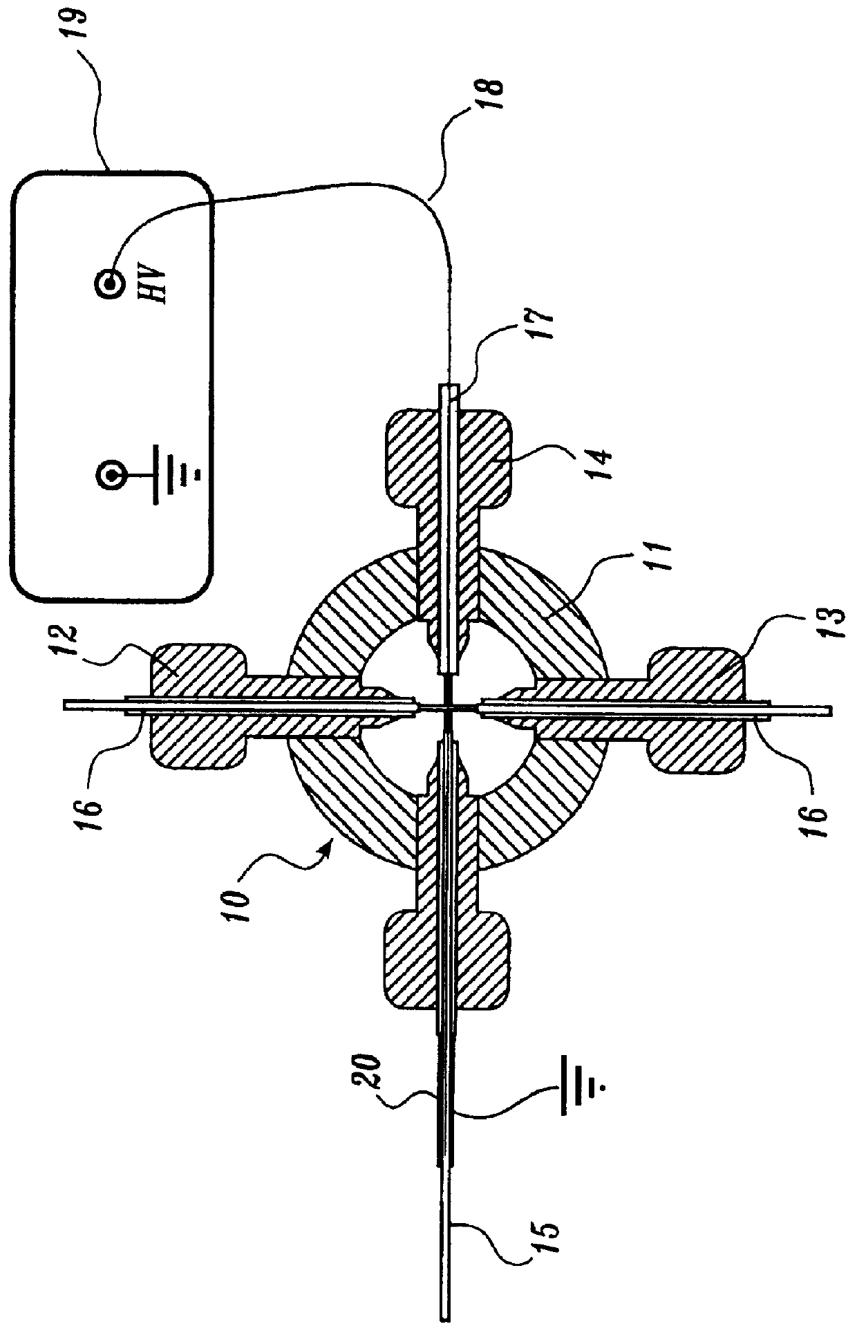
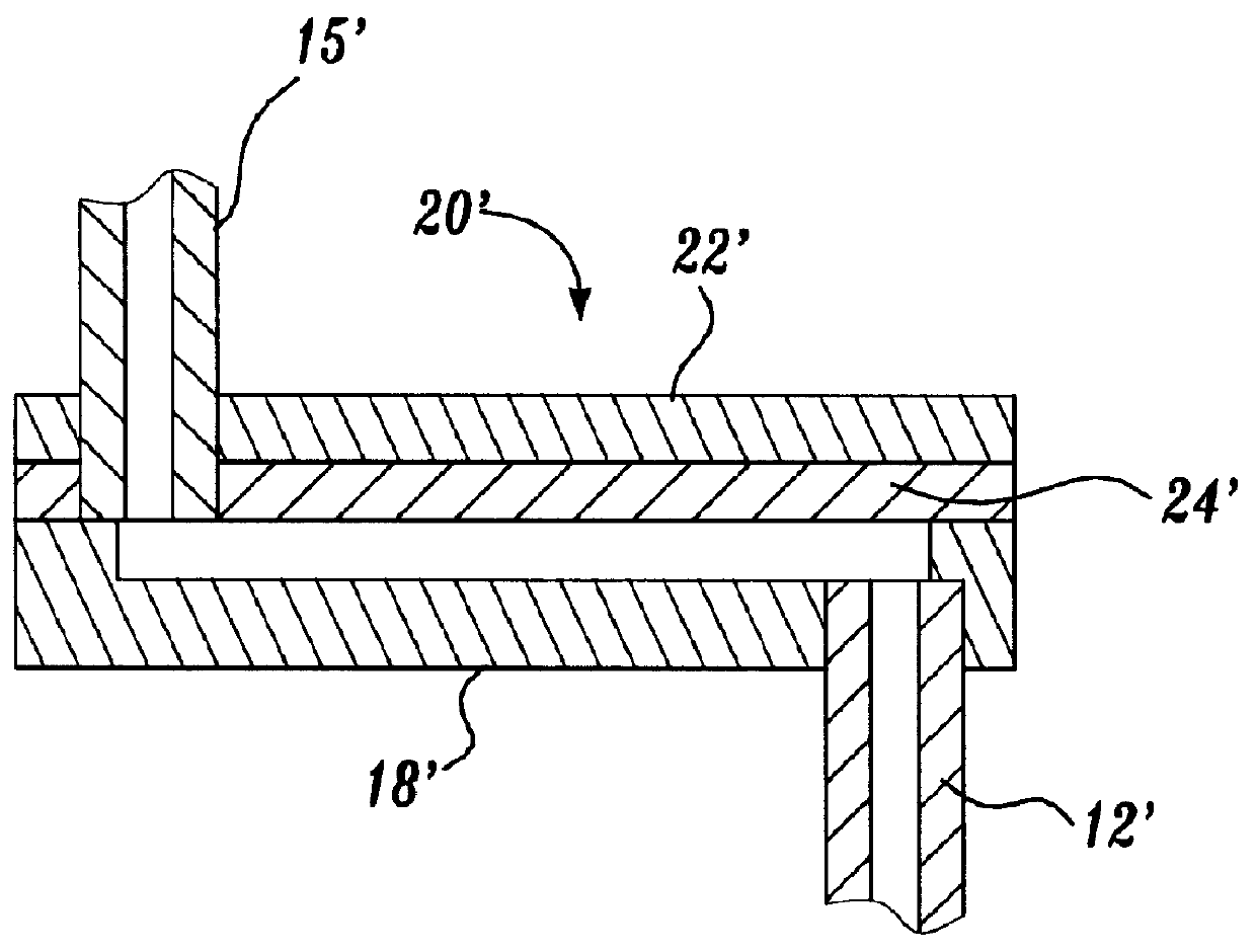
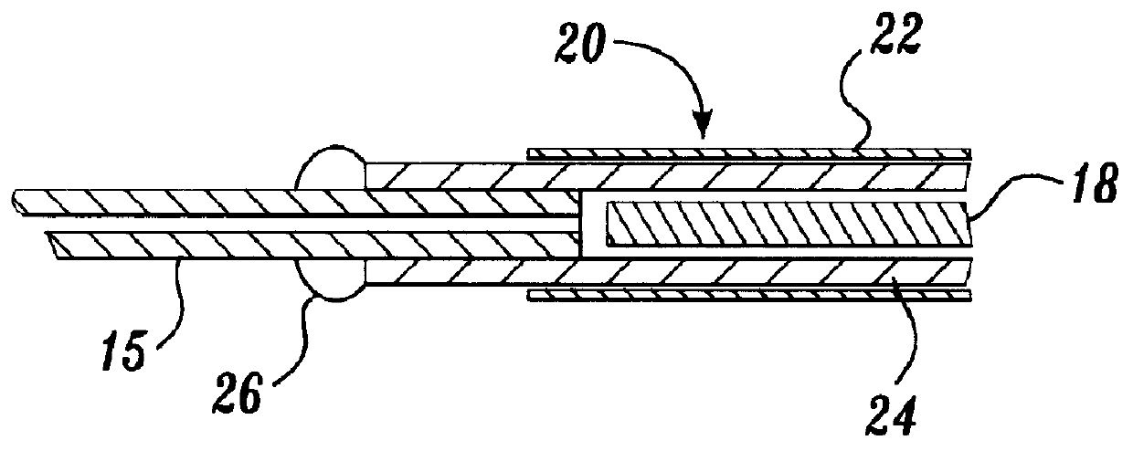
In this example, the construction and operational characteristics of a representative ion source of the present invention are described. Generally, the ion source includes a capacitor having a concentric cylindrical configuration that includes a central electrode and a surrounding cylindrical electrode separated by a fused silica dielectric material. The representative ion source constructed as described below can be interfaced to a mass spectrometer as described in Example 2.

A representative ion source was constructed from a fused silica capillary, 75 .mu.m i.d..times.185 .mu.m o.d..times.5 cm (Polymicro Technologies Inc., Phoenix, Ariz.) by inserting a 50 .mu.m diameter platinum wire (Goodfellow Corp., Berwyn, Pa.) into the fused silica capillary and then surrounding the capillary / electrode assembly with a 27 gauge stainless steel capillary tube (Small Parts Inc., Miami Lakes, Fla.). An alternative oute...

example 2

Interfacing a Representative Ion Source to a Mass Spectrometer

A representative ion source of the present invention, constructed as described above in Example 1, was interfaced with a mass spectrometer as described in this example.

A Finnigan MAT TSQ 7000 (Finnigan Corp., San Jose, Calif.) triple quadrupole mass spectrometer having an API interface was used for all experiments described in the following examples except where the Sciex API III+ mass spectrometer (PE-Sciex, Thornhill, Ontario, Canada) is specifically noted. The mass spectrometer's original ES ionization rear block, containing the high voltage portion of the interface, was replaced by the ion source construction described in Example 1 above. The heated capillary portion of the Finnigan interface was retained without modification. The capillary was held at a temperature of 180.degree. C. except for the 50 .mu.L / min high flow experiment, which was performed at 250.degree. C. Voltages applied to the lenses and mass filters ...

example 3

Representative Ion Source Signal Linearity

The linearity of ion signal was determined using a representative ion source of the present invention constructed as described in Example 1 and interfaced to a commercially available mass spectrometer as described in Example 2 by the procedures described in this example.

A positive ion calibration curve was constructed by directly infusing a solution of angiotensin I using a syringe pump and a 75 .mu.m i.d. fused silica transfer line at a rate of 200 nL / min in 1:1 acetonitrile / water 0.5% acetic acid. Three determinations were made for the peak height of m / z 433 at each concentration level by averaging three centroid scans, 350 to 600 m / z at 1.0 sec / scan, with an electron multiplier setting of 1400 V. Concentration detection limits for infusion were calculated based on a criteria of 3.times. the standard deviation of the baseline noise. For the high flow experiment at 50 .mu.L / min, infusion experiments were carried out with angiotensin I, 1 pm...


PUM


Abstract

A device and method for forming ions by inductive ionization is disclosed. The device is an ion source that includes a capacitor having a pair of electrodes separated by a dielectric material. The method of the invention uses the capacitor-based ion source to form positive and negative ions including multiply-charged ions.

Description

FIELD OF THE INVENTIONThe present invention relates generally to a device and method for forming ions from neutral molecules and, more particularly, to an ion source that forms ions by inductive ionization.BACKGROUND OF THE INVENTIONMass spectrometry relates to the determination of the molecular weights of individual molecules by their conversion into ions in vacuo and then subjecting the ions to electric and / or magnetic fields to determine their mass. Ion formation is a prerequisite to the determination of a molecule's molecular weight by mass spectrometry.Classical ionization methods involve gas phase interactions of the molecule to be ionized with electrons, as in electron impact ionization (EI), photons as in photo ionization (PI), and other ions as in chemical ionization (CI). These ionization methods result in the formation of ions from the neutral molecule by a variety of mechanisms, including the removal from or addition of an electron or a positively charged entity (e.g., a...

Claims


Application Information

Patent Timeline
Patent Type & Authority Patents(United States)
IPC IPC(8): H01J49/26
CPCH01J49/16
Inventor WANG, HOULEHACKETT, MURRAY
Owner UNIV OF WASHINGTON
Why Eureka
Try Eureka