

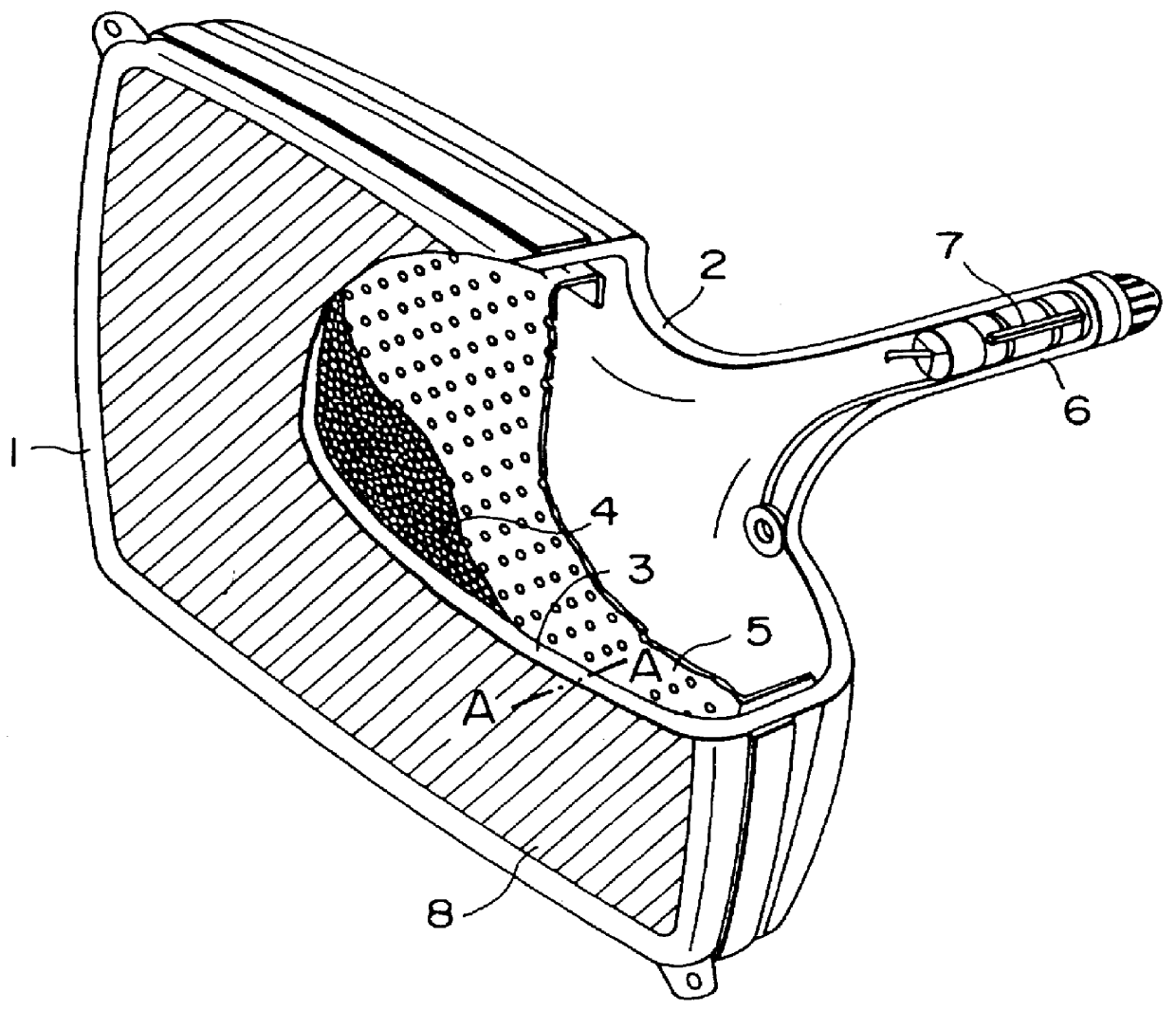
Conductive anti-reflection film
a technology of anti-reflection film and conductive film, which is applied in the direction of electrical connection of cathode ray/electron beam tube, instruments, optical elements, etc., can solve the problems of large scale equipment required to form a conductive film, aef cannot be sufficiently prevented, and adversely affect the electronic unit or the like that is disposed around the cathode ray tub
- Summary
- Abstract
- Description
- Claims
- Application Information
AI Technical Summary
Benefits of technology
Problems solved by technology
Method used
Image

Examples
first and second embodiments
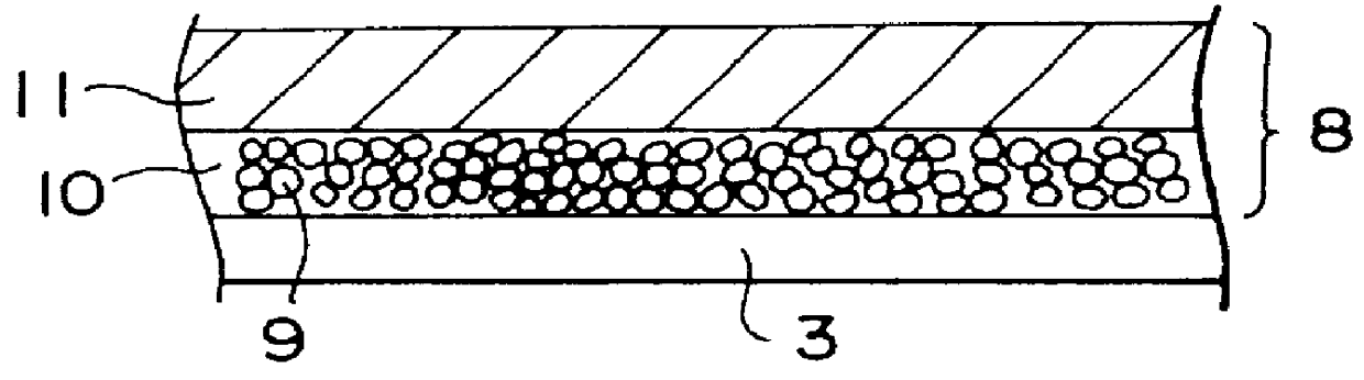
0.5 grams of particles of a silver compound such as Ag.sub.2 O, AgNO.sub.3, or AgCl was dissolved with 100 grams of water. As a result, a first solution was prepared. 100 grams of silicate solution composed of 8 parts by weight of methyl silicate, 0.03 parts by weight of nitric acid, 500 parts by weight of ethanol, and 15 parts by weight of water was mixed with 0.01 parts by weight of NaBH.sub.4 or LiAlH.sub.4 as a reducing agent. As a result, a second solution that contains NaBH.sub.4 and a third solution that contains LiAlH.sub.4 were prepared. Thereafter, the outer surface of the face panel (a 6-inch car-equipped panel) of a cathode ray tube that had been assembled was buffed with cerium oxide so as to remove rubbish, dust, and oil therefrom. Thereafter, the first solution was coated on the outer surface of the face panel and thereby a first coated film was obtained by the spin coat method in the conditions that the surface temperature of the panel (coated surface) was 45.degree....
third and fourth embodiments
0.01 to 0.05% by weight of diethanolamine (DEA) or 3% ammonium solution was mixed with 100 grams of silicate solution composed of 8 parts by weight of methyl silicate, 0.03 parts by weight of nitric acid, 500 parts by weight of ethanol, and 15 parts by weight of water. As a result, a fourth solution that contains DEA and a fifth solution that contains ammonium were prepared.
Thereafter, the fourth solution (in the case of the third embodiment) or the fifth solution (in the case of the fourth embodiment) was coated on the first coated film formed on the outer surface of the face panel (6-inch car-equipped panel) of the cathode ray tube that had been assembled as with the first embodiment by the spin coat method. As a result, a second coated film was formed. Next, the first coated film and the second coated film were sintered at a temperature of 210.degree. C. for 30 minutes.
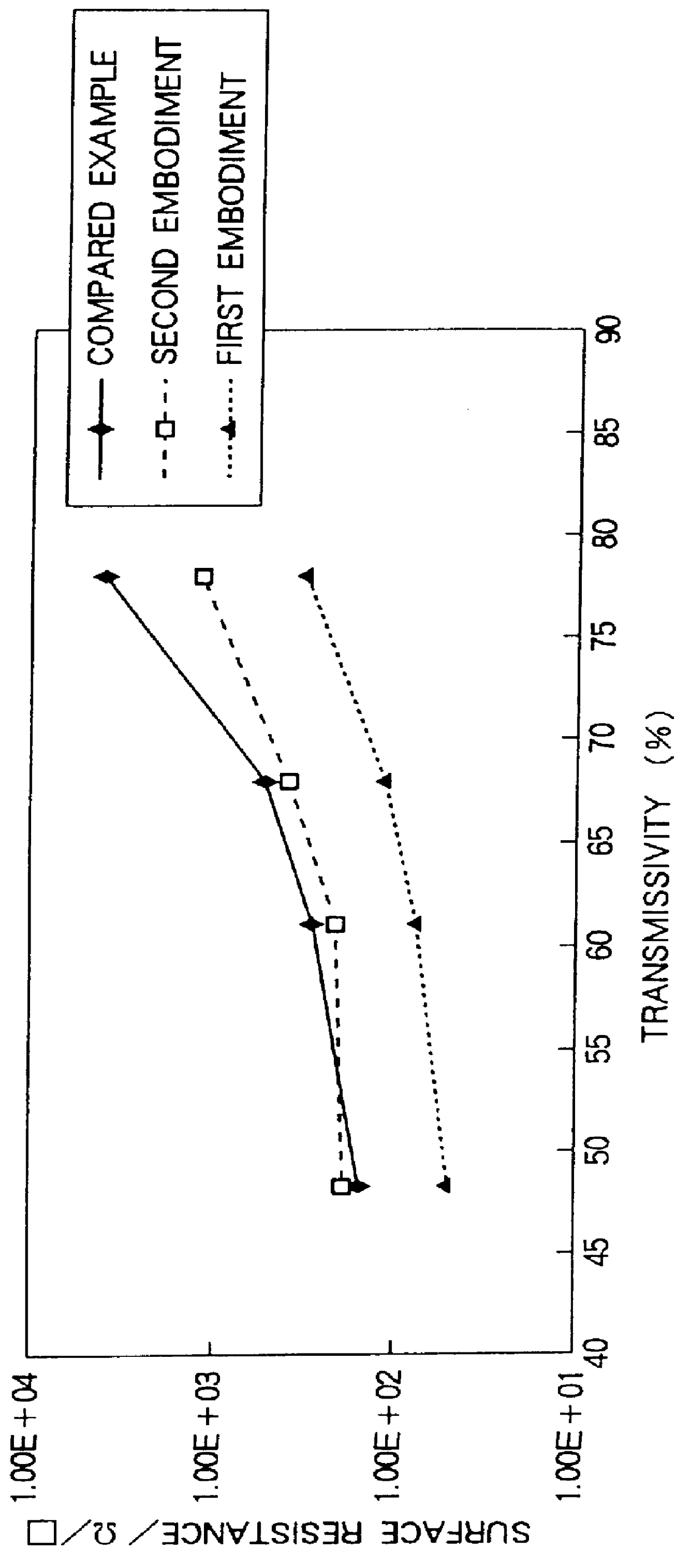
Thereafter, the transmissivity of light (white light) and surface resistance of the conductive anti-reflection f...
fourth embodiment
Referring to FIG. 4, it is clear that the surface resistance of the conductive anti-reflection films of the third and fourth embodiment is much lower than the surface resistance of the conductive anti-reflection film of the compared example while a sufficient transmissivity for a high transparency is accomplished.
Thus, with the conductive anti-reflection film according to the present invention, the surface resistance can be remarkably decreased while a sufficient transmissivity for a high transparency is accomplished. Consequently, in a cathode ray tube such as a TV Braun tube or a computer monitor, the AEF can be almost prevented.
In addition, since the conductive anti-reflection film according to the present invention can be produced by the coating method (wet method) that is simple and effective, the conductive anti-reflection film that is excellent in production and cost performance can be provided.
Thus, when the conductive anti-reflection film according to the present invention ...
PUM
| Property | Measurement | Unit |
|---|---|---|
| Electrical conductor | aaaaa | aaaaa |
| Refractive index | aaaaa | aaaaa |
Abstract
Description
Claims
Application Information