
Thermal reactor with self-regulating transfer mechanism

a transfer mechanism and reactor technology, applied in the direction of steam generation using hot heat carriers, inorganic chemistry, corrosion prevention, etc., can solve the problems of chemical nickel deposits in corrosive atmosphere limitations, flowmeters and expensive monitoring equipment, and transfer is not as precisely controlled

Inactive Publication Date: 2001-06-05
CERAMIC OXIDES INT
View PDF1 Cites 41 Cited by
  • Summary
  • Abstract
  • Description
  • Claims
  • Application Information

AI Technical Summary

Benefits of technology

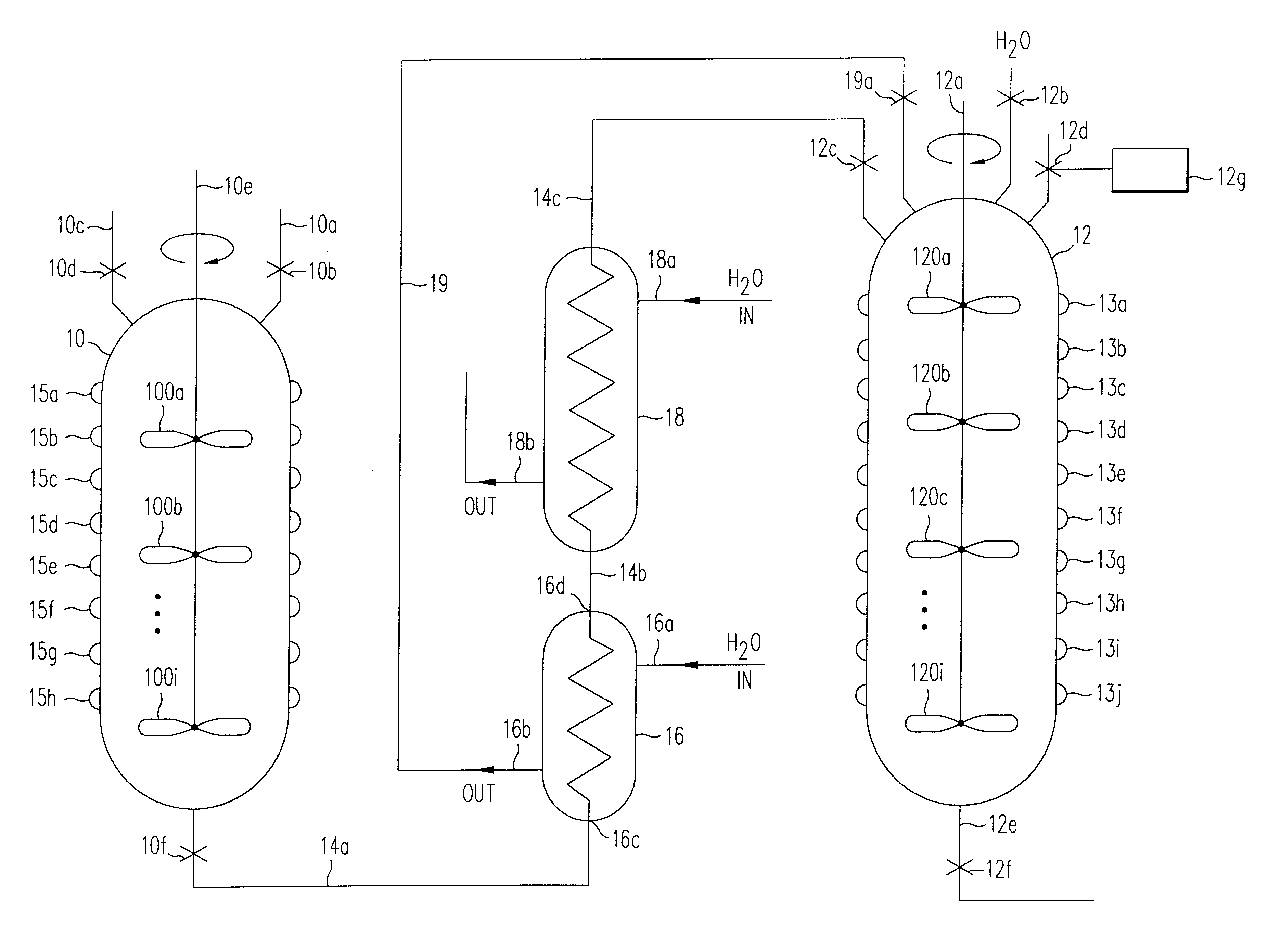
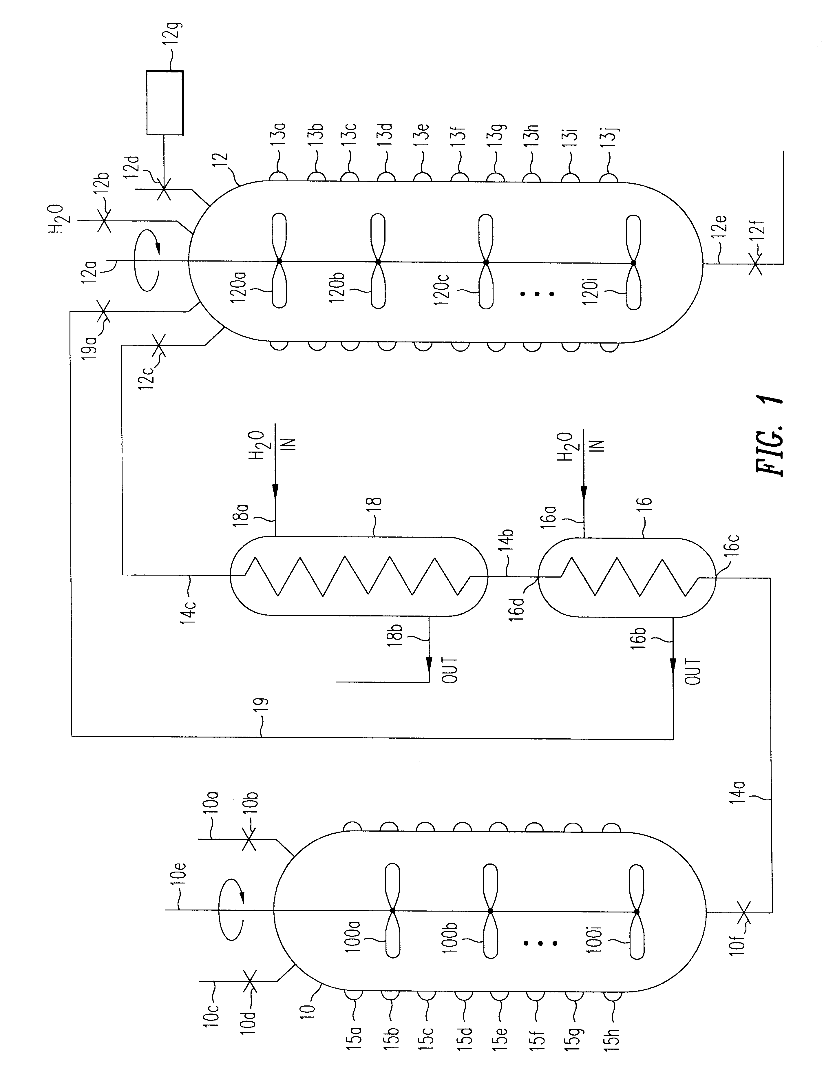
An initial pressure difference now exists between the receiving vessel and the autoclave. The reaction product slurry in the autoclave is then transferred via a pipe and heat exchanger(s) to the receiving vessel due to this initial pressure difference. An increased rate of transfer through the heat exchanger(s) causes the temperature of the reaction product slurry entering the receiving vessel to rise. The slurry entering the hot receiving vessel generates more steam and pressure at a higher slurry temperature than at a lower slurry temperature. Since an increased transfer rate causes the pressure within the receiving vessel to rise, which in turn lowers the transfer rate, the present system maintains a self-adjusted pressure difference between the two vessels to control the transfer rate of the slurry.
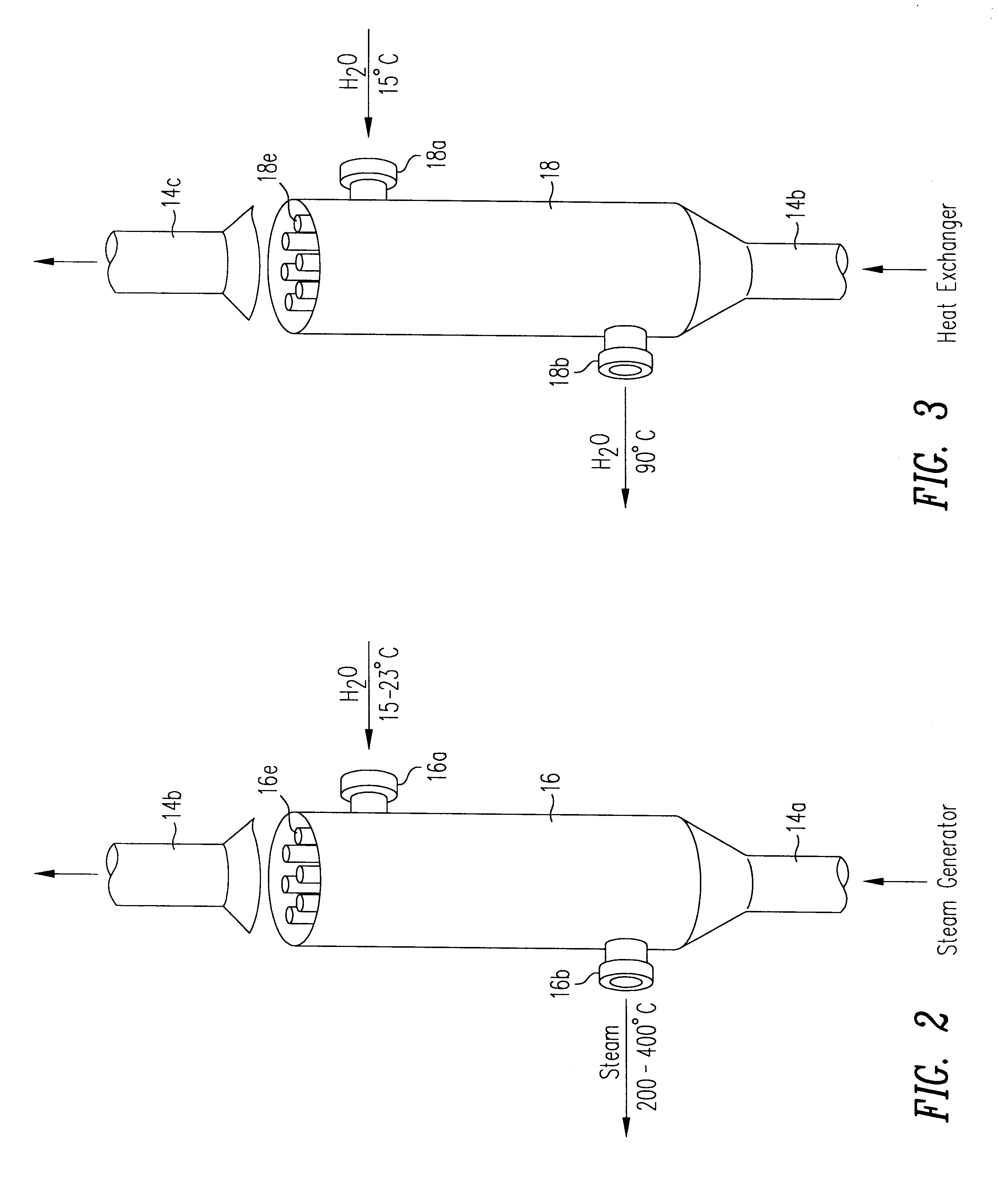
Additionally, a two-stage heat exchanger is preferably used, where a first heat exchanger acts as a steam generator by converting an externally supplied flow of water into steam as the water cools the hot slurry from the autoclave. This steam is supplied to the receiving vessel to additionally control the pressure differential between the two vessels. The flow rate of cooling water through the steam generator is used to vary the temperature of the steam generated (a higher flow rate of cooling water gives a lower steam temperature) and the temperature of the slurry, where a lower steam temperature reduces the pressure in the receiving vessel so as to increase the slurry flow rate. A higher steam temperature will raise the pressure in the receiving vessel and slow down the slurry flow rate.
The self-adjusting and self-siphoning reaction system described allows the autoclave to discharge the slurry at a desired flow rate without the prior art requirement of continuously monitoring and controlling the flow rate of reaction product and the relative pressures of the autoclave and receiving vessel.

Problems solved by technology

This embodiment avoids the use of a control circuit but has the potential disadvantage that the transfer is not as precisely controlled as with a control circuit.
However, this embodiment has the disadvantage of requiring a flowmeter and expensive monitoring equipment in order to trigger a pressure relief valve if, for example, the flow enters the turbulent regime.
The limitations of chemical nickel deposits in a corrosive atmosphere are those inherent in any thin protective film over a substrate where the film is susceptible to attack.
Specifically, almost all inorganic acids and short-chain carboxylic acids exhibit penetration rates which are too large for practical use of electrodeless coatings.
The same limitations apply, of course, to an electroplated nickel coating, except that as the thickness of the nickel coating is increased, the nickel coating may be more economically applied by electrodeposition.
Plate made by electrodeless deposition, which is relatively brittle, is not recommended in applications where flexing or resistance to violent shocks is required.
Also, the plating usually develops a crack pattern which destroys the protective value of the nickel-alloy film.
Ordinarily, chemical nickel coating is more expensive than electrodeposition primarily because the reducing agent, namely, sodium hypophosphite, is more costly than electric power.
Furthermore, a fine grain carbon steel, such as WB36, has a tensile strength which diminishes only 12% between 100.degree. C. and 350.degree. C., and a maximum of 28% between 100.degree. C. and 450.degree. C., a regime wherein stainless steel's tensile strength drops dramatically, necessitating thick stainless steel autoclave walls and exacerbating the heating / cooling time problem.
Carbon steel alone not only suffers an incrustation problem but is also unable to withstand the expected acid pH range (0<pH<7) or alkali pH range (7<pH<14), whereby such acidic or alkali media would attack the carbon steel.
On the other hand, there are certain reactions that are carried out under extreme alkali conditions leading to leaching of the stainless steel cladding where those impurities are consequently leading to an undesired, contaminated end product, as is the case with, for example, Nickel Zinc Ferrite, which is used as a magnetic ceramic for application in the high frequency telecommunications and computer data storage.
By increasing the temperature and the corresponding saturated steam pressures in a reactor system to near critical, at critical, or above critical temperatures, the required dimensioning and ruggedness of autoclaves and heat exchangers become extraordinary, and investment costs cannot be balanced against the economic justification of producing fine ceramic crystals resulting from such reaction processes.
Due to the large pressure differential, the flow of reaction products through line 14 will be relatively swift, which may make this transfer system unsuitable for those reaction products whose crystal structures would degrade when subjected to rapid changes in temperature and pressure.
In addition, the prior art grinding procedure yields crystals of nonuniform and differing sizes even though the resulting materials are substantially fine.
This creates certain problems in using these crystals to form finished products.
In particular, ceramic materials are known to be brittle despite their other desirable characteristics.
However, nonuniformity of ceramic crystal size yields a nonuniform bonding force which in itself relates to discrepancies in the atomic structure of the ceramic crystal making up the ceramic materials.
Apparently the bonding energy between nonuniform crystals is unable to find a so-called harmonic neighbor thus leading to spontaneous fatigue because of the differences in the bonding energy between different size crystals within the material.
At this stage of the technological development of materials from ceramic crystals, several companies have acquired improved crystal size uniformity obtained using a grinding process but still the uniformity is not sufficient to allow the proven material to be used in high technology applications such as, for example, blades for jet engines.

Method used


Image

  • Thermal reactor with self-regulating transfer mechanism
  • Thermal reactor with self-regulating transfer mechanism
  • Thermal reactor with self-regulating transfer mechanism

Examples


Embodiment Construction

Symbols, Units and Conversion Factors

.DELTA..sub.f G.degree.=Gibbs energy of formation, 25.degree. C., I=0; kJ mol.sup.-1

.DELTA..sub.f H.degree.=Enthalpy of formation, 25.degree. C., I=0; kJ mol.sup.-1

S.degree.=Entropy, 25.degree. C., I=0; J mol.sup.-1 K.sup.-1

C.sub.p.degree.=Heat capacity, 25.degree. C.; J mol.sup.-1 K.sup.-1

.DELTA..sub.r G.degree.=Gibbs energy of reaction, 25.degree. C., I=0; J mol.sup.-1

.DELTA..sub.r H.degree.=Enthalpy of reaction, 25.degree. C., I=0; J mol.sup.-1

.DELTA.S.degree.=Entropy change for reaction, 25.degree. C., I=0; J mol.sup.-1 K.sup.-1

.DELTA.C.sub.p.degree.=Heat capacity change for reaction, 25.degree. C., I=0; J mol.sup.-1 K.sup.-1

J=joules; cal=calories

kJ=kilojoules=1000 joules

I=ionic strength, mol kg.sup.-1

K=273.15+.degree. C., C.=celsius

mol=gram molecular weight

Q=equilibrium quotient, or product

K.degree.=intrinsic equilibrium constant, 25.degree. C., I=0

R=gas constant: 8.3143 J mol.sup.-1 K.sup.-1 ; 1.987 cal mol.sup.-1

g=gaseous form

s=solid form

a...


PUM

PropertyMeasurementUnit
Temperatureaaaaaaaaaa
Pressureaaaaaaaaaa
Flow rateaaaaaaaaaa

Abstract

A reaction product is formed and transferred from an autoclave to a receiving vessel at a laminar flow rate, using a self-adjusting transfer mechanism. A specific amount of water in the receiving vessel is heated and vaporized prior to the reaction product transfer to raise the pressure in the receiving vessel to saturation pressure. A flow passage between the autoclave and the receiving vessel is now opened, and a resulting pressure differential between the autoclave and the receiving vessel initiates the transfer process. A heat exchanger cools the reaction product flowing from the autoclave to the receiving vessel, where the amount of cooling is dependent upon the transfer rate of the reaction product. An increased transfer rate will cause the hotter reaction product entering the receiving vessel to increase the pressure inside the receiving vessel, thereby reducing, or self-adjusting, the transfer rate. The heat exchanger may also generate steam which is fed into the receiving vessel to adjust the pressure in the receiving vessel and thus adjust the transfer rate of the reaction product.

Description

1. Technical FieldThis invention relates to the formation of reaction products such as ceramic, magnetic, electrolyte, electrode and other powders, to the use of high temperatures to disintegrate unwanted compounds, and to a structure employed for these purposes which may operate at near critical, critical or supercritical temperatures and the corresponding saturated pressures of the working fluids.2. Description of the Related ArtIn my earlier U.S. Pat. Nos. 4,238,240, 4,366,121, 4,545,970, 4,753,787, 4,912,078, 4,983,374 and 5,026,527, I describe numerous structures and processes for forming reaction products. These patents are hereby incorporated by reference.In my '240 patent I disclose a method for forming a reaction product in which the reaction constituents are mixed in an autoclave. The mixed reaction constituents are then reacted for a selected time to form reaction products, and the reaction products are transferred, at the end of the reaction, from the autoclave to anothe...

Claims


Application Information

Patent Timeline
IPC IPC(8): B01J19/18B01J3/04B01J19/02B01J3/00B01J3/02C01B13/36C01G53/00F22B1/16F22B1/00F28F19/06F28F19/00F28D7/16F28D7/00
CPCB01J3/008B01J3/02B01J3/04B01J19/0066B01J19/02B01J19/1862C01B13/366F22B1/16F28D7/16F28F19/06B01J2219/0009B01J2219/0236Y10T137/86196Y10T137/0396
Inventor KRIJGSMAN, PIETER
Owner CERAMIC OXIDES INT
Learn More