(a) An adjustable
orifice plate having one or a multiplicity of adjustable orifices that can intercept the liquid flow into or across the
diameter of the flow channel to impose a sufficient pressure drop thereon to initiate flash-down, or to control its flow rate automatically by controlling the pressure on the liquid into or along the length of the flash-down channel, or of several parallel flash-down sub-channels, or as sensed by a
pressure sensor or temperature sensor located downstream of the
orifice plate, or by two or several such sensors located on either side of the point of flash-down and at the end of the channel or sub-channels to detect or measure pressure change (.
DELTA.P) or temperature change (.
DELTA.T) during flash-down. Adjustment of the orifice diameters responsive to these measurements would provide one means for controlling the flash-down process or the
evaporation rate, and this may be automated to improve the flash-down process stability. The adjustable
orifice plate applied herein is as disclosed in U.S. Pat. No 5,968,312. It permits improved flash-down control of a wide range of heated liquid flows to accommodate a wide range of fluctuation in the rate of
heat rejection from a power generation
plant or another heat supplying process. Additional means for control or adjustment of such flows are the elevation of the orifice plate relevant to the vessel height, the
feed pressure or temperature below the orifices, the
vapor pressure or temperature in the liquid-vapor separation vessel and the degree of flash-down being controlled. Another orifice controlling procedure is to combine a fixed-orifice plate and the adjustment of a feed control valve upstream thereof albeit not as effective as using the above adjustable orifice plate. Generally, the objective is to maintain or control singlephase liquid flow up to the orifice plate and two-phase thereafter to the vessel;
(b) By the addition of a surface
active agent, or a
foaming agent or foaming dispersant to the liquid at a selected concentration before it reaches the flash-down point, to stabilize two-phase vapor-liquid flow during liquid flash-down or to improve or maintain the stability of the two-phase flow regime or to prevent coalescing of
liquid phase or separation of
liquid phase from the two-phase regime within the flash-down channel. Addition of a surface
active agent or
foaming agent also reduces the liquid holdup and the static pressure within the upflow channel or sub-channels; this also reduces the pressure drop for two-phase flow through such channels, and it also provides for a more intimate or
mixed flow by creating foaminess which improves the process of reaching or approaching liquid-vapor thermal equilibration within the channel and also in the separation vessel;
(c) By
insertion of a bundle of tubes in-side the flash-down channel, or sub-dividing it, to provide parallel flow sub-channels of selected
diameter for the control and maintenance of continuous two-phase flow produced within each sub-channel, by selecting the
diameter of the sub-channels, e.g., a close-packed bundle of parallel tubes or pipes packed for example in a tight triangular array, and wherein each tube communicates with an orifice or an adjustable orifice plate to deliver a flashed-down flow of liquid and vapor into each tube or sub-channel, wherein each tube or sub-channel is designed or selected for, or provides for a well dispersed two-phase vapor-liquid flow along its length and for preventing coalescence of liquid phase or back-flow thereof, or to reduce slip-flow thereof, the objective being to bring about or approach
thermal equilibrium between the
vapor phase and the residual liquid phase at the outlet end of each tube or sub-channel by causing further flash-down of this liquid phase. Means for providing adequate mixing or dispersion of the vapor and liquid phases to promote thermal equilibration also include selecting the diameter and length of the sub-channels, the selection of sub-channel material, construction and flow-channel configuration, for example the use of corrugated plates of fiberglass plastic or
metal secured
ridge-to-
ridge to form parallel sub-channels across the diameter of the channel, or the use of bundles of square
pipe or hexagonal
pipe having four or six flat sides and packed closely to reduce the overall diameter of the
main channel. Also, the option of such
pipe being twisted around its axial center to provide for vortex mixing of the two-phase flow along its length or parts thereof. The flow diameter of the flash-down channel or sub-channels depends in part on the
feed temperature and the degree of flash-down or the flash-down .
DELTA.T or .DELTA.P available. In general, the channel diameter would be proportional to the .DELTA.P. The objectives are to improve flash-down efficiency or the
thermal efficiency by
phase mixing or dispersion, and to approach completion of flash-down, or to obtain a controlled residual
liquid temperature and assure that the vapor thereby produced has a temperature close to that of the residual
liquid temperature. This objective would also improve
thermal efficiency of flash-down. It would also improve the subsequent separation of the residual liquid phase from the
vapor phase produced, and the breaking-up of foam to facilitate complete separation of residual liquid before the condensation of vapor in the next step of this procedure. To achieve an improved approach in equilibration of vapor and residual liquid temperatures, or a reduction in their
temperature difference, the walls of the packed tube bundles may be indented at selected intervals to promote
phase mixing, or mixing elements may be inserted such as
helical-twisted baffles similar to U.S. Pat. No. 3,457,982. Such modifications of flow through a tube or channel can be applied to provide for either two-phase flow with mixing of the phases or for phase separation by imposing a single-axial vortex flow whereby the liquid is directed into an annular layer in shear-flow with the vapor in the core of the vortex, or widening the
helical insert for dual axial
spiral flow to cause
phase mixing imposed on the two-phase flow, or an alteration of these
modes of flow in sequential channel sections.
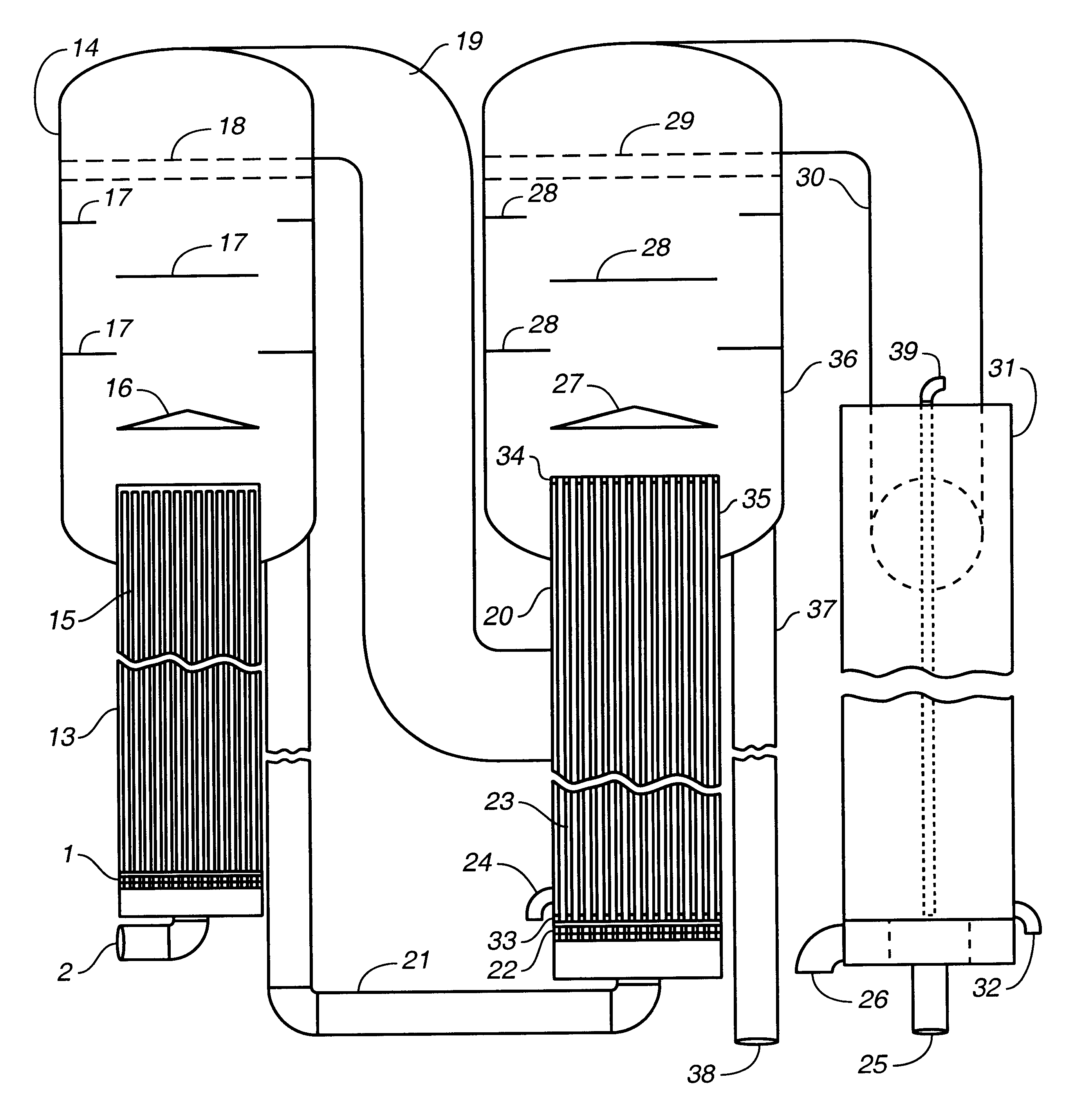
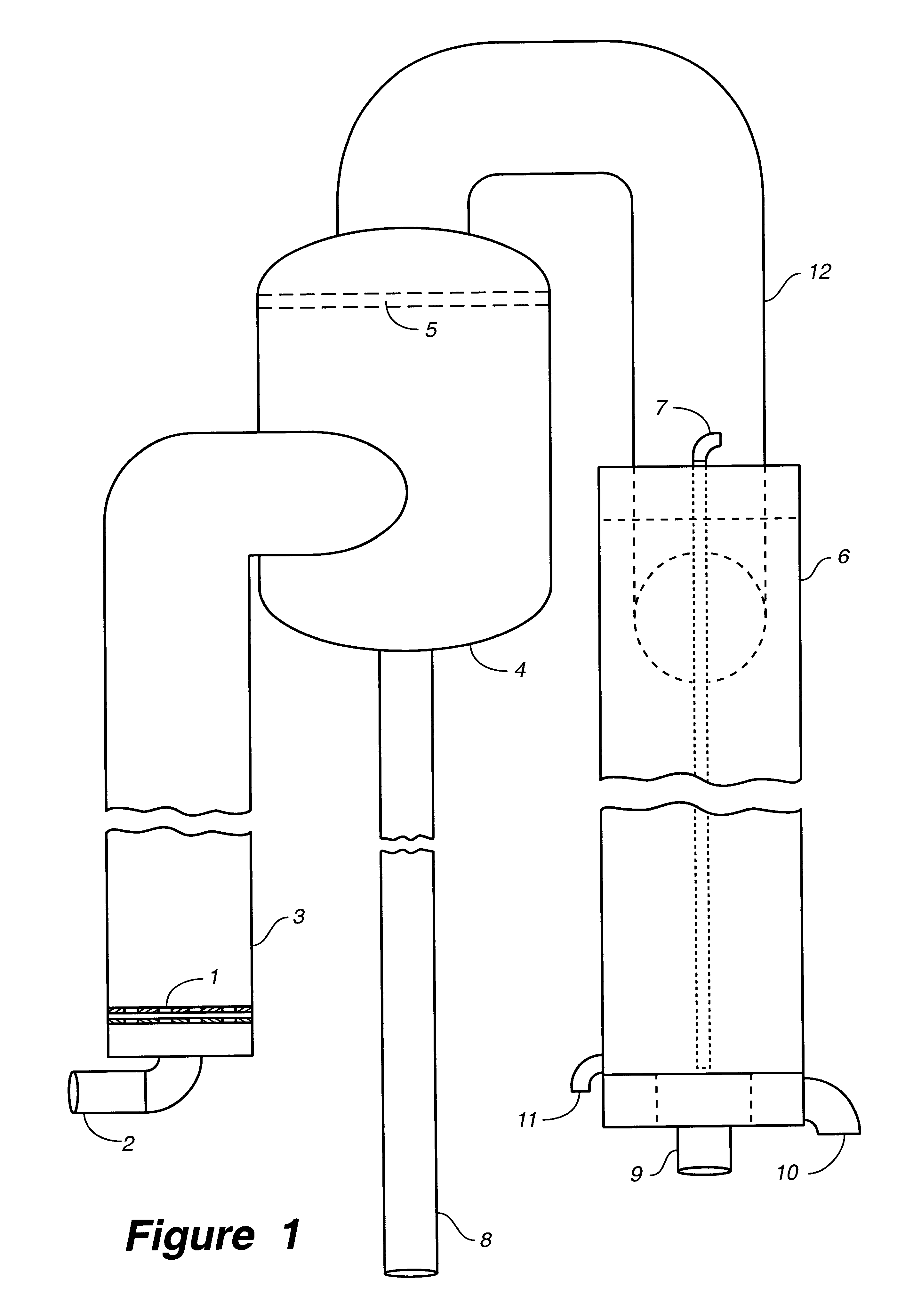
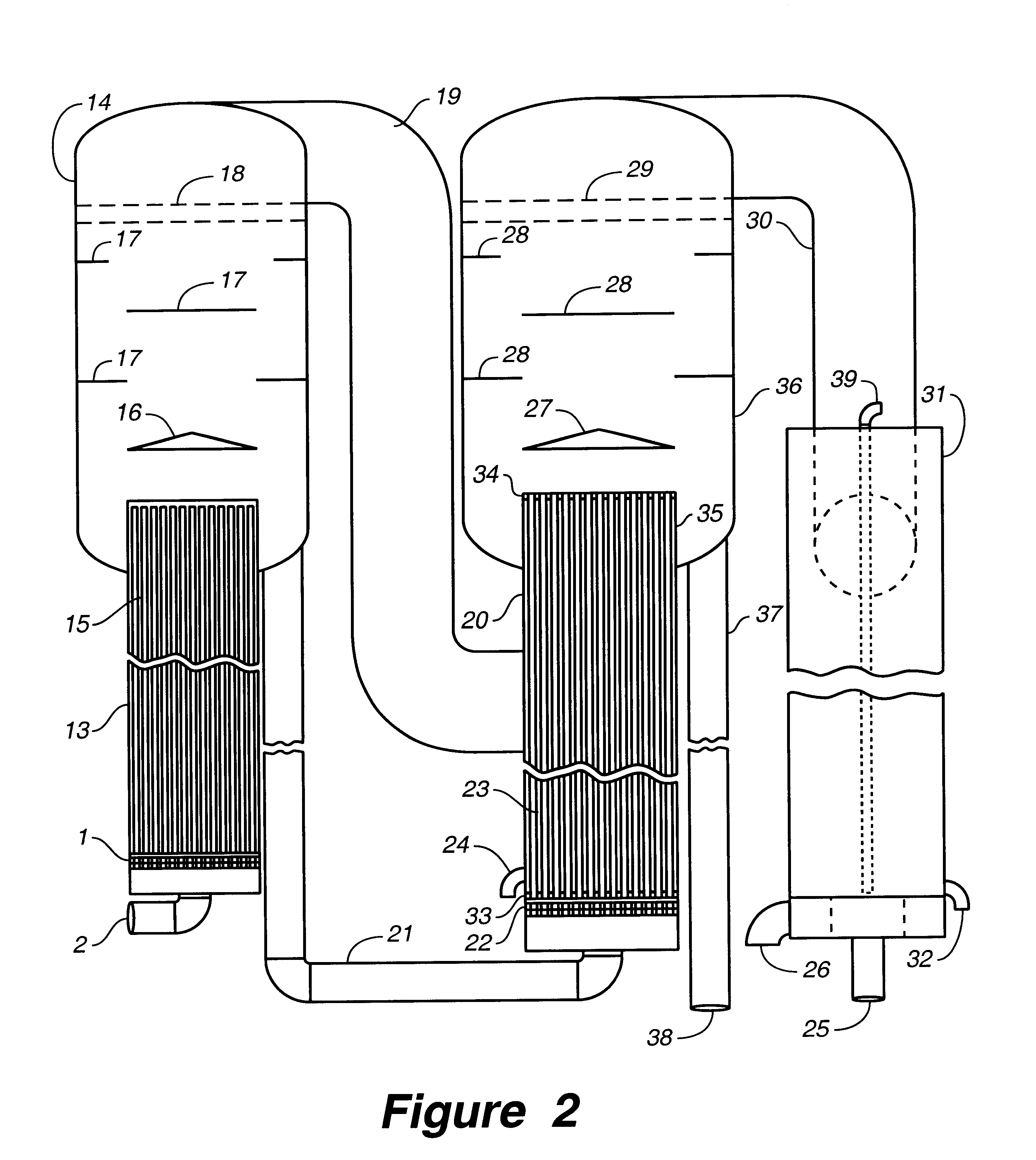
4. Separation of the vapor phase, or the nearly saturated vapor, from the residual liquid occurs or is imposed adjacent to the outlet end of the flash-down channel, which liquid is by then cooled by flash-down to a selected or controlled residual
liquid temperature or pressure; and this is followed by using or condensing of the vapor phase or the vapor in either a condenser as option one (i.e. in a condensing
heat exchanger) or by its condensation in an
evaporator as option two (e.g. a condensing and evaporating
heat exchanger); in either option condensation occurs under a vacuum or reduced pressure, yielding a distillate. The flash-down vapor thus condensed forms a first distillate having a weight about equal to the weight of the initial vapor produced by flash-down. The amount of this first distillate depends on the selected residual liquid temperature or the degree of flash-down, and on the rate of flow and the temperature of the original liquid or brine or
seawater and on whether option one or option two is applied. If option one is applied, this first distillate is the total distillate to be produced and the amount of first distillate is maximal; but it will be lower than the total distillate produced if option two is applied i.e. if condensation of the vapor occurs in an evaporator wherein additional vapor is produced from the residual brine discharged from the barometric evaporator, or from another liquid feed, and if this vapor from the evaporator is also condensed into a second distillate which would increase the total distillate obtained to more than the first distillate.
5. As an option two, the further evaporation of the residual brine discharged from the barometric evaporator or flash-down evaporator may be applied in a
vertical tube evaporator (VTE) which can be either an upflow VTE and either a single-effect or multi-effect (ME), or it may be a downflow VTE as for example an evaporator design based in part U.S. Pat. No. 5,853,549 for a multi-stack VTE (or MS-VTE) or it could be a conventional downflow ME-VTE, dependent on the temperature and volume of the available warm feed liquid
stream and on the product volume needed. In the option two procedure, the residual liquid or brine discharged from the barometric evaporator may be flashed-down further and then applied as the feed liquid for the VTE or ME-VTE series, to be further evaporated as it flows through the tubes in either downflow or upflow VTE
modes and with this evaporation being driven by the heat of condensation provided by condensing the above first vapor on the outside surfaces of these tubes, and so on along the ME series applied. Since the VTE would be at a lower pressure and temperature than the barometric evaporator and depending on their elevations, there may be no need for pumping this feed. The vapor produced in the first VTE amounts to about the weight of the first vapor plus the vapor produced during the further flash-down of the residual liquid from the barometric evaporator, and this amount can be substantially more than the usual amount obtainable from a conventional VTE or ME-VTE since the degree of this further flash-down may be selected independently; also, this further flash-down can be controlled by using the adjustable orifice plate of U.S. Pat. No 5,968,312. The total desalinated product would then include the condensate from the first vapor plus those of the vapors produced in the VTE or VTE series, and would be substantially more than that of option one, and progressively more for additional effects. Several options can thus be applied for the condensation of the vapor produced in the combination of a barometric evaporator and VTE options.

