

Method and apparatus for producing a high-velocity particle stream
a high-velocity particle and stream technology, applied in the field of high-velocity particle stream production methods and equipment, can solve the problems of localized material failure and removal, large amount of abrasive particles required per area of coating removal, and large amount of abrasive particles, etc., to achieve uniform particle spread, increase surface area, and improve productivity
- Summary
- Abstract
- Description
- Claims
- Application Information
AI Technical Summary
Benefits of technology
Problems solved by technology
Method used
Image

Examples
example 2
Zinc Primer Removal
Comparison of One Embodiment of the Present Invention with a Conventional Surface Preparation Apparatus / Method
The conventional device comprised a 4 / 16" diameter (or #4) converging / diverging dry abrasive blasting nozzle, which is common in the industry. The nozzle was driven by 100 psi air at a flow-rate of 90 ft.sup.3 / min to propel 500 lbs / hr of 16-40 mesh size abrasives on to the test surface.
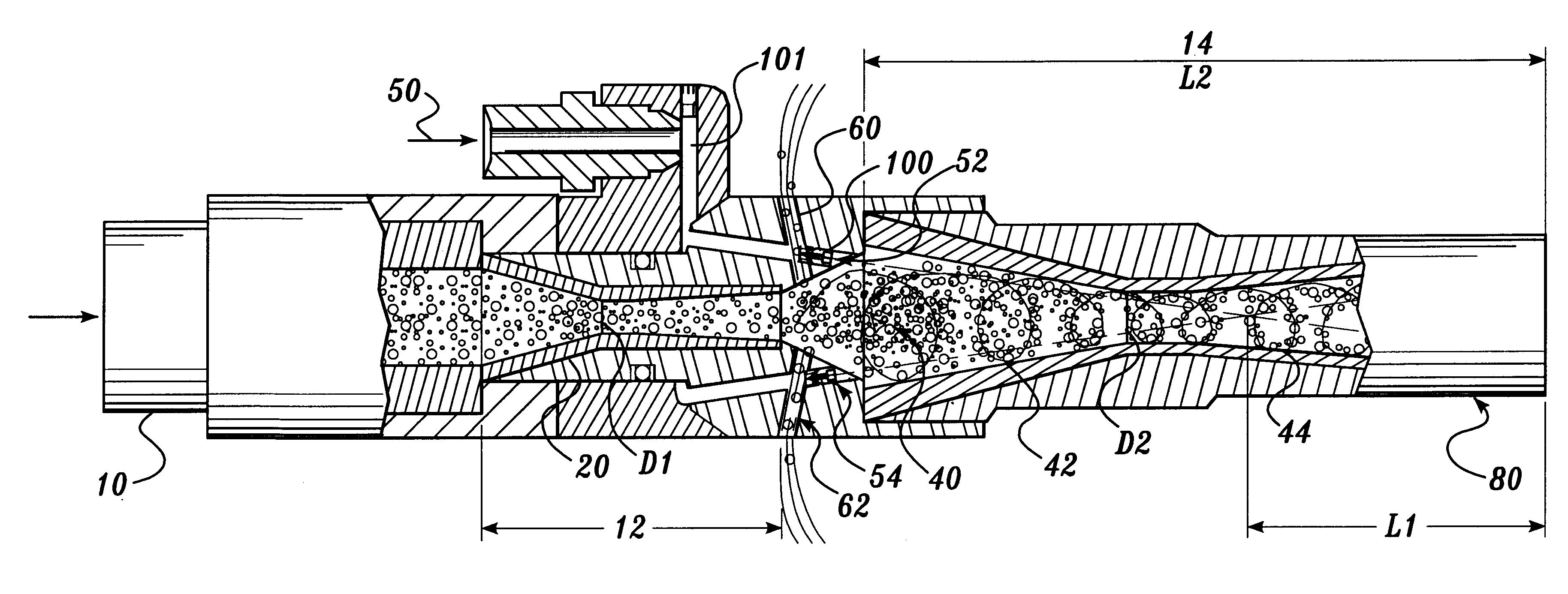
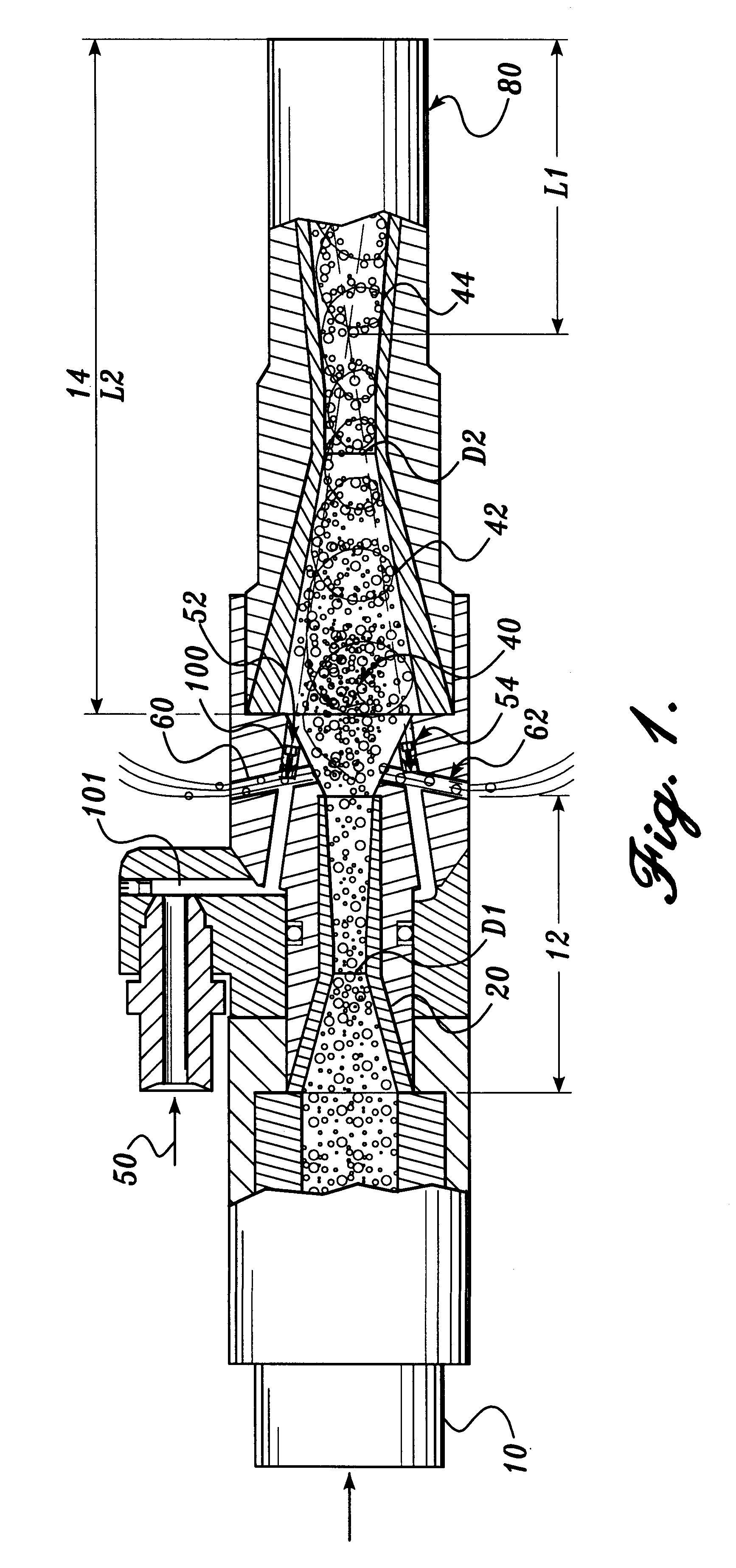
The present invention apparatus comprised the conventional device described above, serving as its first acceleration stage, driven by the same air pressure, same air-flow rate and delivering the same abrasives mass-flow at identical particle size to the second acceleration stage. The second acceleration stage is water jet driven with a jet velocity of about 2,200 ft / sec. Vortex action was not externally promoted, i.e., no additional fluid was injected from the side into the mixing chamber to amplify vortex action in the mixing chamber.
The results are summarized below:
example 3
Mill-Scale Removal
Comparison of One Embodiment of the Present Invention with a Conventional Surface Preparation Apparatus / Method
The conventional device comprised a 4 / 16" diameter (or #4) converging / diverging dry abrasive blasting nozzle, which is common in the industry. The nozzle was driven by 100 psi air at a flow-rate of 90 ft.sup.3 / min to propel 500 lbs / hr of 16-40 mesh size abrasives onto the test surface.
The present invention apparatus comprised the conventional device described above, serving as its first acceleration stage, driven by the same air pressure, same air-flow rate and delivering the same abrasives mass-flow at identical particle size to the second acceleration stage. The second acceleration stage is water jet driven with a jet velocity of about 2,200 ft / sec. Vortex action was not externally promoted, i.e., no additional fluid was injected from the side into the mixing chamber to amplify vortex action in the mixing chamber.
The results are summarized below:
example 4
Zinc Primer Removal
Comparison of One Embodiment of the Present Invention with a Conventional Surface Preparation Apparatus / Method
The conventional device comprised a 3 / 16" diameter (or #3) converging / diverging dry abrasive blasting nozzle, which is common in the industry. The nozzle was driven by 100 psi air at a flow-rate of 50 ft.sup.3 / min to propel 260 lbs / hr of 16-40 mesh size abrasives onto the test surface.
The present invention apparatus comprised the conventional device described above, serving as its first acceleration stage, driven by the same air pressure, same air-flow rate and delivering the same abrasives mass-flow at identical particle size to the second acceleration stage. The second acceleration stage is water jet driven with a jet velocity of about 2,200 ft / see. Vortex action was promoted, through the injection of additional compressed air producing a rotation effect amounting to 0.17 inch-pound per pound of air entering the first acceleration stage.
The results are ...
PUM
| Property | Measurement | Unit |
|---|---|---|
| Angle | aaaaa | aaaaa |
| Angle | aaaaa | aaaaa |
| Angle | aaaaa | aaaaa |
Abstract
Description
Claims
Application Information