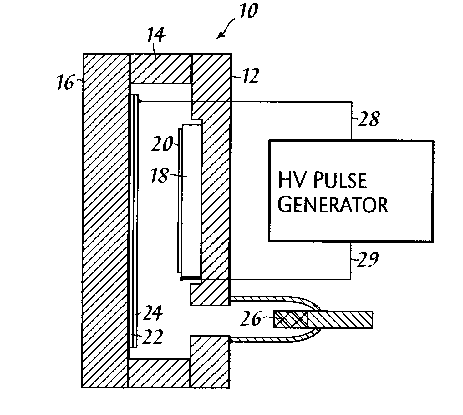
Referring to FIG. 1, lamp
assembly 10 includes base 12, transparent plate 16, and spacers 14. These elements form a structure which can maintain high vacuum. Seals at the interfaces with spacers 14 may be any conventional
vacuum tube seals such as glass
frit or
epoxy. Base 12 may be formed from
metal,
ceramic or transparent glass or
ceramic material. Transparent plate 16 is preferably a glass having a high
thermal conductivity, such as
borosilicate glass.
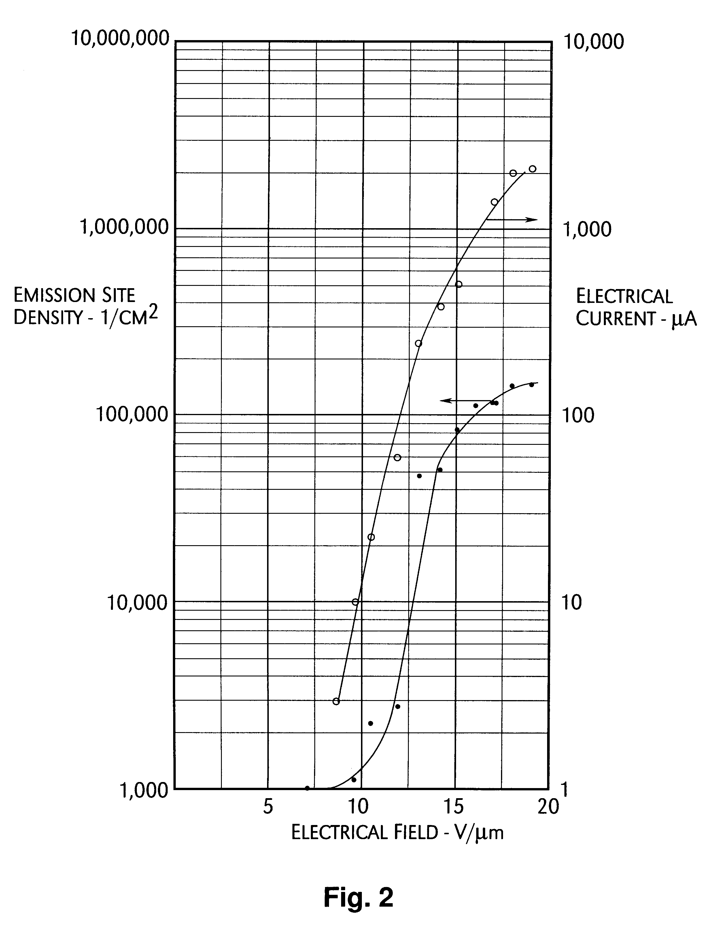
Examination of the curves shows that driving the
diode having the
cold cathode at low
electrical field strength produces only
low emission site density. This results in low light output from a device using such cathode. Experiments have shown that at low site density "hot spots" are present on the cathode. This produces burning of the cathode and burning of the phosphor opposite the hot spot in the
diode configuration. The solution to the problem of low site density or hot spots has been found to be the use of high-
voltage pulses. Reference to FIG. 2 shows that at
high voltage, the emission site density becomes orders of magnitude greater. For example, at an electrical field of 12 volts per
micrometer the emission site density was about 2800 sites per cm.sup.2. At a field of 15 volts per
micrometer, the emission site density had increased to about 85,000 sites per cm.sup.2. However, emission current had also become much larger--increasing from about 60 microamperes to about 500 microamperes.
Power consumption of the
diode under DC operation per cm.sup.2 of area would be [500.times.10.sup.-6.times.10 kV.times.1 / 0.0035] 1.4 kilowatts, which would cause severe overheating at the electrodes in a short time and require too much power. It has been found, however, that the application of
high voltage pulses at low
duty cycle overcomes both the problem of
low emission site density and excess
power consumption at the electrodes. Neglecting
capacitance losses, for example, with a
duty cycle of 1 percent, the power requirement will be in the range of 14 watts.
Voltage of pulses and duty cycle are selected to produce the brightness desired from phosphor layer 24 of FIG. 1, keeping in mind the limitation of heating of the electrodes. A duty cycle of one percent or less can produce a bright lamp using presently available phosphors having normal efficiency. The frequency of the pulses may be in the range from about 20 Hz to about 20 MHz but is selected to produce a light output that is effective for the use intended. Excess
flicker or variation in intensity can easily be avoided by increasing frequency of pulses. Preferably,
pulse frequency is from about 1 Hz to about 10 kHz.
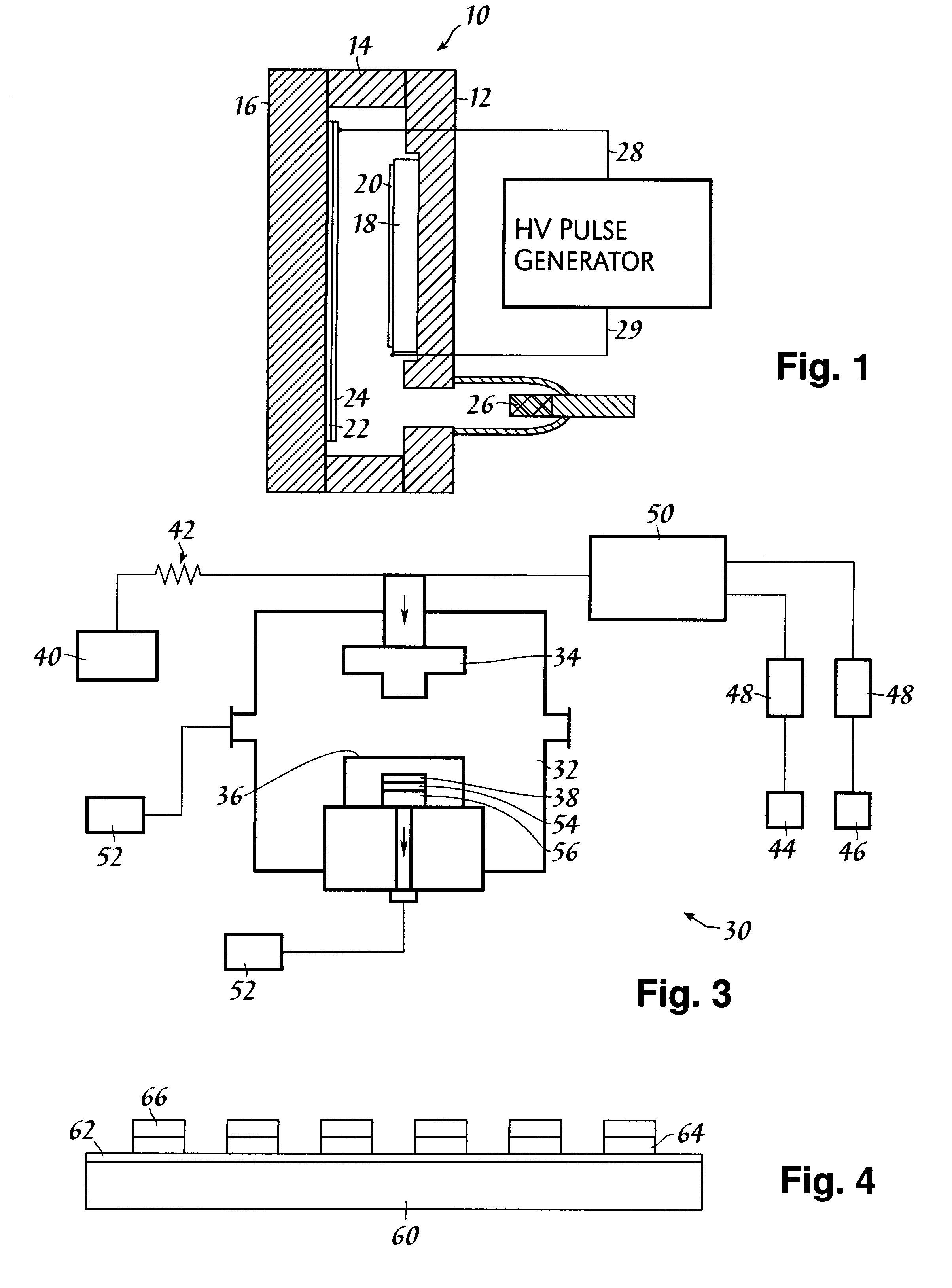
Grid 36 is formed as a mesh, preferably made from wire having a
diameter of about 0.3 mm. The wire material used is preferably
tungsten. The mesh includes a plurality of openings, each opening having a width of about 0.1 mm to about 5 mm and a length in about the same range of dimensions. Preferably, grid 36 is heated. Heating is achieved by the
discharge current. The grid temperature is increased to above 1100.degree. C. Grid 36 then behaves as a hot element to increase the
diamond film growth rate on substrate 38. The high temperature also allows formation of
film material having a structure which is effective as a
cold cathode electron emitter. Preferably, the grid temperature should be above 1300.degree. C. for effective cold
electron emission and may be increased to as high as about 2500.degree. C.
Apparatus of FIG. 1 includes only one cathode surface. The size of this surface is limited by the area of low-effective field emission
work function diamond or carbonaceous material that can be produced on a single surface. Production of wafers having low effective field emission
work function diamond coatings up to about 10 inches in
diameter is presently available for diamond made by
laser ablation. For larger areas than available from one
wafer, a plurality of cathode areas may be used. FIG. 4 shows such cathode. Also provided in FIG. 4 is a means to avoid the destructive effects of arcing from cathode to anode should arcing occur for any reason. Such arcing may be caused, for example, by gas evolving from phosphors or other materials in a lamp
assembly.
Resistor 64 preferably has a resistance in the range of 1 to 100 megohms. The value of resistance is selected such that about 50 percent of the
voltage drop under arcing conditions would occur across
resistor 64. The preferred value of resistance increases as operating current through the cathode decreases. The benefit of
resistor 64 is to decrease the risk of destruction of the cathode in the presence of arcing conditions. There may be an efficiency loss in the range of 10 percent to 50 percent from the presence of the integral
resistor.

