Optical imaging device

a technology of optical imaging and interference signals, which is applied in the field of optical imaging devices, can solve the problems of large variation, difficult to reproduce a two-dimensional image from the obtained interference signals, and inability to provide such substances

Inactive Publication Date: 2003-05-13
UNIVERSITY HOSPITALS OF CLEVELAND CLEVELAND +1
View PDF7 Cites 277 Cited by
  • Summary
  • Abstract
  • Description
  • Claims
  • Application Information

AI Technical Summary

Problems solved by technology

Such a great variation is a problem.
It is impossible to provide such substances at the narrow probe tip to be introduced into the patient's body cavity.
Because the mirror rotates first in one direction and then in the other, it is difficult to reproduce a two-dimensional image from the obtained interference signals.
If the device uses an interference signal obtained by scanning in only one direction, it will neglect half the actually obtained signal data.
Such a decrease in resolution and dynamic range is a problem.
In such cases, to display interference signals accurately, it is impossible to use the interference signals obtained in time series, because the interference signals are linear with respect to time, and because the interference location is nonlinear with respect to time.
In such cases, if the device fails to indicate accurately the interference location and the detection position, the image produced will be warped, and it is impossible to accurately measure length with a scale.
In such cases, if the frequency characteristics of the demodulator circuit are set so that the demodulator can detect all possible interference frequencies in a wide range, then the detection will include excess noise, and result in a decrease in the signal-to-noise ratio.
The inferior signal-to-noise ratio is a problem.
In these cases, the Doppler frequency may also vary; therefore, setting the frequency characteristics of the demodulator will pose a similar problem.
The work is troublesome.
Such a nonlinear relationship is difficult to handle.
The inferior signal-to-noise ratio, aggravated by setting the frequency characteristics of a demodulator, is a problem.
Such difference causes a significant error, and that is a problem.
Since OCT, in principle, detects the correlation between the reflection intensity on the optical path and the optical path length, presence of two faces with intense reflection in the vicinity will cause a degradation in the amount of optical power available for image formation.
They will also result in the formation of reflections at the probe sheath surfaces which could be large compared to any tissue reflections, and will thus tend to overwhelm the dynamic range of the detection electronics and make it difficult to display weak tissue reflections on the same screen as the strong sheath reflections.
Furthermore, multiple reflections may form between the reflecting surfaces, resulting in the generation of ghost images of the tissue where no actual reflection surface exists.
The observation light, which is light scattered and reflected by the living body, is relatively weak light when compared with the above mentioned reflection intensity, the ghost will considerably deteriorate the observation performance.
This is especially damaging if the ghost image appears at the same location as the actual tissue image, in which case there is no simple way to separate them.
The prior art suffers from problems that when the endoscope with the probe inserted through its insertion opening is inserted into a body cavity or when the probe is bent, the rotating support for the optical element at the tip end comes into contact with the interior of the outer sheath and damages the interior, that optical characteristics of the outer sheath are degraded by irregular reflection of lights at the damaged portion, and that the observation quality deteriorates as the OCT irradiation light emitted by the optical element and observation light reflected by the living body are shielded.
Furthermore, probe sheaths made from such materials as fluorine resin and polyamide have very poor optical quality, such that they have randomly spaced internal index of refraction boundaries, internal striations, and particulate scatterers which act to degrade the wavefront of light propagating though them and to scatter a significant portion of light into unpredictable directions.
Since the probe design depends upon light being directed to a diffraction-limited focussed spot in the tissue and then being re-coupled into the single mode fiber on the return path, any passage through elements which degrade the optical wavefront or scatter light severely degrades the re-coupling of image-forming light into the probe and the heterodyne efficiency of the OCT interferometer.
Therefore, when the number of times of reflection on the end surface of the optical element is even less than three times, it can be almost the same level as the strength of the signal of the living body and causes difficulty in observation.
Particularly, there are problems when the shape of the sheath is cylindrical because it is difficult to treat to prevent reflection from the surface of the sheath, and it is easy then for light reflected three times to overlap on the observing position.
One more problem of the above mentioned end optical system is the structure of the end optical system in that the light outgoing from the single mode fiber is reflected on the boundary surface of the optical element and the reflected light is directly returned to the single mode fiber 205.
Therefore, if the structure of the optical system is the structure of once reflection, it will be hard to see an observing screen.

Method used


Image

  • Optical imaging device
  • Optical imaging device
  • Optical imaging device

Examples


first embodiment

The first embodiment is able to compensate for the stress-induced birefringence of the fiber bent and varied in quality so that it may be introduced into the patient's body cavity, and to compensate for the stress-induced birefringence of the fiber varied in quality, depending on the rotation of radial scanning in the patient's body cavity.

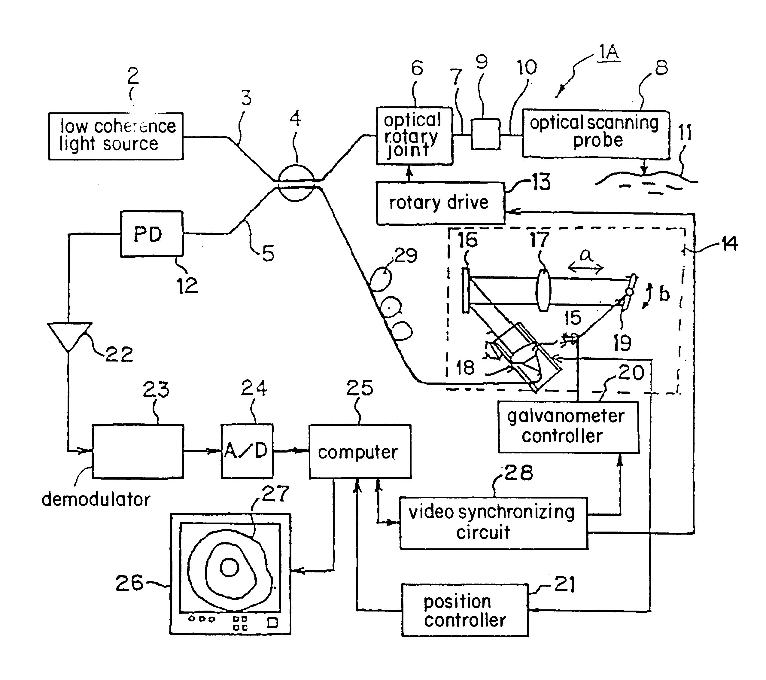
FIG. 6 shows a composition of an optical imaging device in the first embodiment of the present invention. FIG. 7 shows an endoscope through which the first embodiment is passed.

Optical imaging device 1A (optical tomography imaging device), shown in FIG. 6, includes superluminescent diode (SLD) or a semiconductor optical amplifier (SOA) based low coherence light source 2 that emits amplified spontaneous emission (ASE). This low coherence light source 2 has a central wavelength of 1300 nm and an optical bandwidth of 50-70 nm, for example. It produces low coherence light that causes interference only when the optical path lengths of the interferomete...

third embodiment

The third embodiment is able to provide a high-resolution two-dimensional image, by high-speed scanning using optical length-varying means based on the delay line of mirror oscillation type.

Described below is a method of producing a radial image, by scanning of 1 line in the depth direction, and by the use of flexible shaft 40 in optical scanning probe 8 to turn the distal end optical system.

FIG. 14A shows relationships between depth direction scanning position curve 118 obtained by the movement of galvanometer mirror 19 (either from the position encoder signal in the galvonometer, or from the galvanometer driver signal), mirror scanning timing signal 119 obtained by galvanometer controller 20, interference signal 120 (the envelope of the interferogram signal) obtained by depth direction scanning, and line memory 121 storing the interference signal. The abscissa indicates time.

To maximize scanning speed with galvanometer mirror 19, it is effective to use the same waveform in scannin...

second embodiment

the demodulator 23 which preserves high signal to noise ratio even in the event of nonlinear reference arm scanning is the coherent tracking demodulator illustrated in FIG. 28. As shown in FIG. 28, The input signal from the amplifier is first band-pass filtered using cascaded high-pass filter 201 and low-pass filter 202 set to pass the entire frequency content of the desired portion of the nonlinearly modulated interferometric signal, Df. The band-passed signal then serves as the input to two mixers 205 and 206. A reference signal generator 203 produces a frequency-modulated reference signal whose frequency is proportional at every instant to the derivative of the position of the reference delay scanner, which is calculated to be equal to the instantaneous Doppler shift of the reference arm light. This signal is mixed with the band-passed interferometric signal in mixer 205 to generate the in-phase component I of the demodulated signal. A second copy of the reference signal is delay...


PUM

PropertyMeasurementUnit
incident angleaaaaaaaaaa
angleaaaaaaaaaa
central wavelengthaaaaaaaaaa

Abstract

An Optical Coherence Tomography (OCT) device irradiates a biological tissue with low coherence light, obtains a high resolution tomogram of the inside of the tissue by low-coherent interference with scattered light from the tissue, and is provided with an optical probe which includes an optical fiber having a flexible and thin insertion part for introducing the low coherent light. When the optical probe is inserted into a blood vessel or a patient's body cavity, the OCT enables the doctor to observe a high resolution tomogram. In a optical probe, generally, a fluctuation of a birefringence occurs depending on a bend of the optical fiber, and this an interference contrast varies depending on the condition of the insertion. The OCT of the present invention is provided with polarization compensation means such as a Faraday rotator on the side of the light emission of the optical probe, so that the OCT can obtain the stabilized interference output regardless of the state of the bend.

Description

1. Field of the InventionThe present invention relates to an optical imaging device which irradiates the subject with low coherence light, to produce a tomogram of the subject, from data on light scattered by the subject.2. Description of Related ArtRecent U.S. Pat. No. 5,321,501, for example, discloses a device which can obtain optical information from the inside of the tissue, in order to diagnose the biological tissue, and which performs optical coherence tomography (OCT) of interference type, using low coherence light, to produce a tomogram of the subject. U.S. Pat. No. 5,321,501 also discloses an optical probe which has a flexible insertion unit to be introduced into the patient's body cavity, and which enables the doctor to introduce the insertion unit into a blood vessel, using an optical probe that includes a single mode fiber for sending low coherence light to the inside so that the doctor can observe the inside of the patient's body cavity, using a catheter or endoscope. W...

Claims


Application Information

Patent Timeline
Patent Type & Authority Patents(United States)
IPC IPC(8): A61B5/00G01B9/02A61B1/00A61B10/00G01N21/17G02B26/10
CPCA61B5/0066A61B5/6852G01B9/02002G01B9/0205G01B9/02061G01B9/02069G01B9/02091G01B2290/65G01B2290/70
Inventor IZATT, JOSEPH A.SIVAK, MICHAEL V.ROLLINS, ANDREWHORII, AKIHIROHIRATA, TADASHIIIZUKA, SHUHEI
Owner UNIVERSITY HOSPITALS OF CLEVELAND CLEVELAND
Why Eureka
Try Eureka