Bipolar electrode having non-conductive electrode substrate and fibrous electrochemically active material

a non-conductive, electrode-based technology, applied in the direction of electrochemical generators, cell components, flat cells, etc., can solve the problems of conductive polymers unsuitable for use as bipolar or end electrodes, relatively poor electrochemical activity of conducting plastic composite electrode materials, and since being replaced, etc., to achieve good mechanical properties, high electrochemical activity, and high conductivity

Inactive Publication Date: 2003-12-02
UNISEARCH LTD
View PDF3 Cites 20 Cited by
  • Summary
  • Abstract
  • Description
  • Claims
  • Application Information

AI Technical Summary

Benefits of technology

Accordingly, it is an object of the present invention to provide an electrode, particularly a bipolar electrode, which

Problems solved by technology

Traditionally, carbon or graphite plates were used, but due to the expense of such plates coupled with their weight and their size which rendered them too bulky for large battery stack construction, these have long since been replaced.
However, due to the fact that conductive polymers can degrade due to thermal or electrical field environments and can be easily attacked by acidic and oxidative electrolytes, it has become apparent that in some applications, the conductive polymers are therefore unsuitable for use as bipolar or end electrodes.
However, to date, such conducting plastic composite electrode materials have relatively poor electrochemical activity when compared to metals such as Cu and Fe which have resistivities of around 10.sup.-4 -10.sup.-6 .OMEGA.cm.
Further, because the composite plastic substrate material used in bipolar electrodes is subjected to an additional heat cycle during the felt bonding process, then such plastic composite material becomes brittle and being present in very thin sheet form as the electrode, often suffers degradation during that additional heat cycle causing voids in the composite material, with the subsequent rejection of approximately half the bipolar electrodes resulting from the felt binding process.
Similar problems arise in the manufacturing of e

Method used


Image

  • Bipolar electrode having non-conductive electrode substrate and fibrous electrochemically active material
  • Bipolar electrode having non-conductive electrode substrate and fibrous electrochemically active material
  • Bipolar electrode having non-conductive electrode substrate and fibrous electrochemically active material

Examples


examples

Basic Electrode Substrate Material

Material A)

HDPE sheets produced by means of compression moulding of HDPE-powder was used for the preparation of carbon black free bipolar graphite felt electrodes. As HDPE-powder, GA 7260H powder, Kemcor Australia was used. The sheets were pressed for 10 minutes in an aluminium mould with the inner mould dimensions of 110.times.100.times.1 mm (l.times.w.times.h) under a pressure of 43 kg / cm.sup.2 and a temperature of 155.degree. C. The mould was preheated for 10 minutes before applying the pressure. After pressing, the mould was quenched in a cold water tank. The physical properties of the obtained polymer sheets are given in Table I.

Material C)

Extruded LDPE-material provided by E-PLAS PTY. LTD., AUSTRALIA with a thickness of 1 mm was used as sheet material for electrode preparation. Physical properties are given in Table I.

Material D)

LDPE sheets produced by means of compression moulding of LDPE-granule was used for the preparation of carbon black f...

examples 1a and 1b

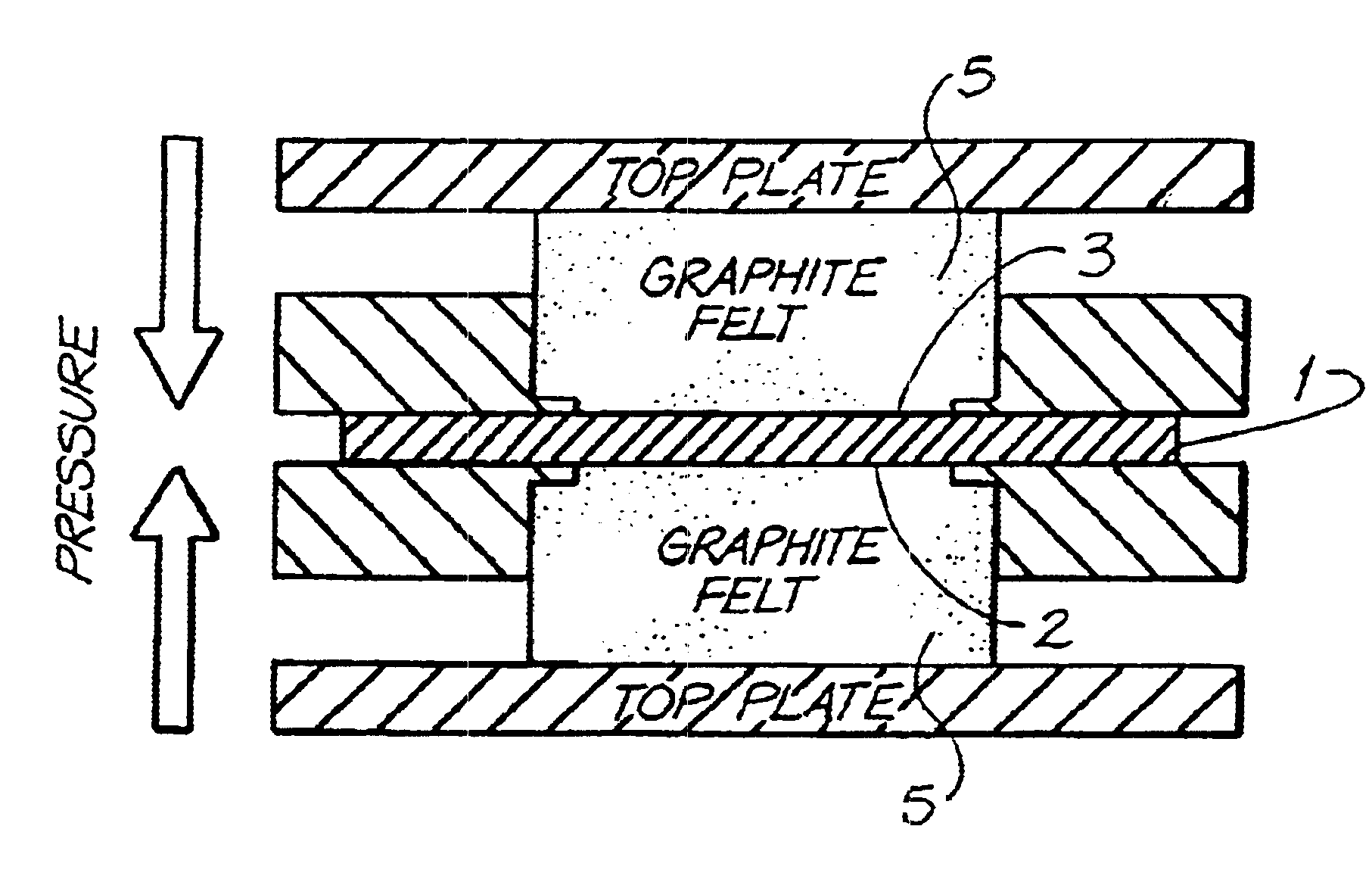
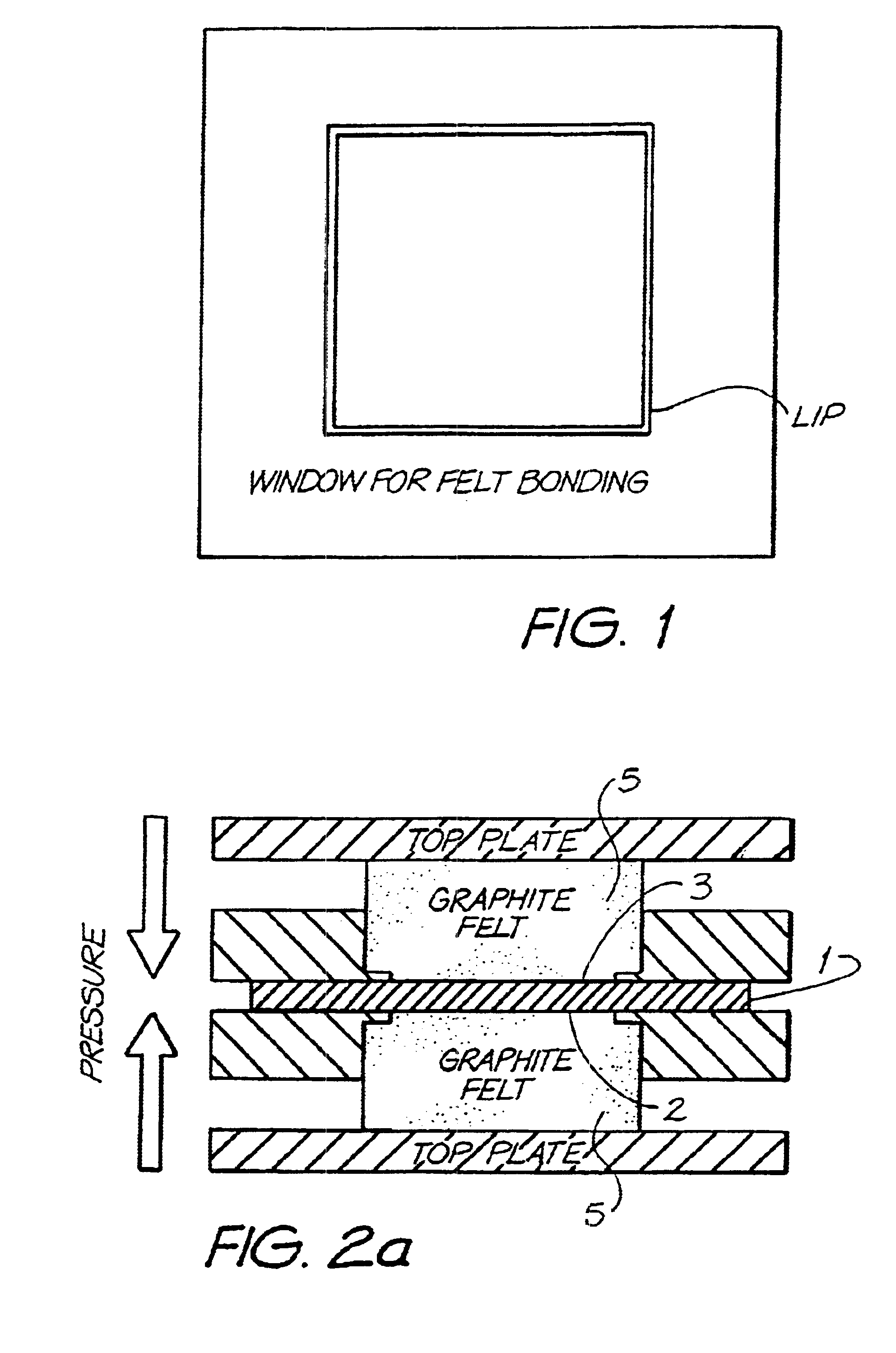
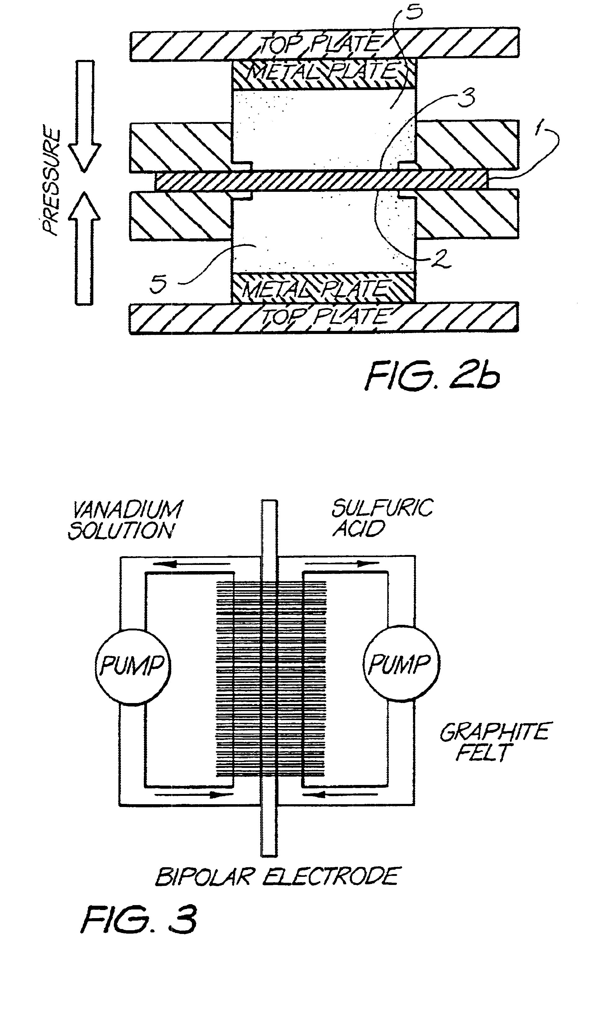
Material A was used as a substrate in the above described felt bonding process I. Felt bonding times were 10 minutes (sample 1a) and 20 minutes (sample 1b). The results of the area resistivity measurements (Test I) are shown in FIG. 6. Electrodes of type 1a were used for permeability tests (Test II and III) which showed no permeability of Vanadium electrolyte during 3 months for Test II and 3weeks for Test III (Experiment was stopped after this period). The set up for permeability Test III is illustrated in FIG. 3. Electrodes of type 1a were also used for overcharging experiments according to Test IV. The carbon black free bipolar electrodes of the invention showed only a small increase of resistance after overcharging (R.sub.OC) and reversibility of the overcharging products after reverse set up (R.sub.rev). Results are shown in Table III. Furthermore, the 1a electrodes were used for evaluation of cell performance described under Test V. These results are illustrated in Table IV. C...

examples 2a-2d

Material C was used as a substrate in the above prescribed felt bonding process I. Felt bonding times were 10 (samples 2a), 20 (sample 2b), 30 (sample 2c) and 40 minutes (sample 2d). Area resistivity measurements (Test I) of the produced electrodes are illustrated in FIG. 6 and show constantly and reasonable low conductivities just for electrodes of type 2d. Due to the required long process times comparable to electrodes of type 1a no further testing (Tests II-V) was performed.


PUM

PropertyMeasurementUnit
Angleaaaaaaaaaa
Molar densityaaaaaaaaaa

Abstract

Electrodes including bipolar composite electrodes and end electrodes are characterized by a layer of electrochemically active material bonded to a first surface of a non-conductive electrode substrate material. In the case of a bipolar electrode, the opposing second surface of the substrate material also carries a layer of electrically active material, the layer of electrochemically active material contacting through said substrate material to provide a current pathway. In the case of an end electrode, the opposing second surface of the substrate material carries a layer of electrically active material, the layer of electrochemically active material contacting the layer of electrically active material through the substrate material to provide a current pathway. Processes of preparing the electrodes and uses of the electrodes in batteries are also disclosed.

Description

This invention relates to electrodes, particularly bipolar electrodes, particularly bipolar composite electrodes characterised by an electrochemically active layer bonded to a substrate material. The electrodes can be used in electrochemical / redox cells and other electrochemical applications.Electrodes are commercially applied in a wide variety of applications including being used in redox flow cells, in battery stacks and other electrochemical applications such as electrodepositing and electrowinning.End electrodes are a type of electrode used in batteries. Typically, the end electrode in a battery stack acts as either an anode or as a cathode and has a current collector on one side. End electrodes, by their nature are connected to a power supply. One form of end electrode is conventionally characterised by an electrode substrate material, onto one side of which is bonded a thin layer of electrochemically active material such as graphite felt or carbon felt, with the other side hav...

Claims


Application Information

Patent Timeline
IPC IPC(8): H01M4/02H01M4/96H01M8/24H01M6/48H01M6/42H01M4/88H01M4/86H01M8/02H01M8/18
CPCH01M4/02H01M4/96H01M8/246H01M6/48Y10T29/49108Y02E60/50Y10T29/49112Y10T29/49115H01M2004/029H01M8/2483H01M8/24
Inventor HAGG, CHRISTOPH M.SKYLLAS-KAZACOS, MARIA
Owner UNISEARCH LTD
Why Eureka
Try Eureka