Optical detection system

Inactive Publication Date: 2004-07-06
CE RESOURCES
View PDF7 Cites 74 Cited by
  • Summary
  • Abstract
  • Description
  • Claims
  • Application Information

AI Technical Summary

Benefits of technology

It is a further object to provide an embodiment of an optical detection system which can perform simultaneous detection in a plurality of samples with reduced scattering and cross-talk.
The present invention is an optical detection system comprising an electromagnetic radiation source, a source radiation focusing and collimating means, a photodetector, an emitted radiation focusing means and a source radiation blocking panel. The radiation source is used to direct source radiation onto a sample which is disposed in a sample platform. The source radiation focusing and collimating means is disposed between the radiation source and the sample for focusing and collimating the source radiation onto the sample. The photodetector is adapted for receiving radiation emitted from the sample which has been focused by the emitted radiation focusing means. The source radiation blocking panel, disposed between the source radiation focusing and collimating means and the sample, is unique in that it is capable of reducing light scattering and interference, such that a clear signal from each individual sample can be obtained by the photodetector.
In the most preferred embodiment, the source radiation focusing and collimating means comprises at least one convergent cylindrical rectangular lens and the source radiation blocking panel comprises a light absorbing panel with at least one pinhole. The samples are contained in channels or tubes aligned in parallel. For simplicity, the samples contained in the various channels or tubes are referred to as sample volumes. In one embodiment, the emitted radiation focusing means is a convex lens, while in another embodiment, it is a convergent cylindrical lens together with an emitted radiation blocking panel having pinholes. This panel with pinholes will be referred to simply as pinholes in the following description. The pinholes may be connected to scanning or conveying means to allow movement. The system may be used for the detection of radiation absorbance or for fluorescence, including epi-fluorescence. Static pinholes for reducing interference and moving pinholes for sequentially and repetitively illuminating selected sample volumes from an array of samples. In the cases of no cross talk between samples or when cross talk can be eliminated, static pinholes are used to reduce interference due to scattered light, while moving pinholes can be used to eliminate cross talk between samples by sequentially and selectively illuminating only the sample volumes to be measured at any instant of time. In this embodiment, the system includes a plurality of sample volumes in parallel comprising: an array of channels, capillaries, flow cells, bands or wells; at least one electromagnetic radiation source; at least one convergent rectangular cylindrical lens to focus electromagnetic radiation; at least one set of static pinholes or moving pinholes; a scanner for moving the pinholes; and at least one detector aligned to receive electromagnetic radiation collected from the sample volumes. The pinholes are placed in between the array of samples and the detector and for between the array of samples and the electromagnetic radiation source. For operation of the system using static pinholes, the number of pinholes should match that of the samples in the array. The electromagnetic radiation energy that reaches each sample volume is homogeneously focused and distributed by the convergent rectangular cylindrical lens through the array of pinholes. Emitted electromagnetic radiation from all of the sample volumes is collected and directed to a detector simultaneously. Pinholes are used to prevent scattered electromagnetic radiation from reaching the detector. In operation of the system using moving pinholes, the number of pinholes is less than that of the sampl

Problems solved by technology

However, the number of capillaries that can be analyzed at one time limits the total throughput of the analysis.
Various methods for acquiring signals from multiple channels have been described; however, the simultaneous detection of the different channels in CAE still presents some problems.
Since relatively heavy components are being moved problems with misalignments of the capillaries relative to the light source are likely to occur.
On the other hand, because the data acquisition is sequential, i.e., the scan modes are from the first capillary to the last capillary in the array, the use for a very large number of capillaries is limited by the observation time needed per capillary.
Loss of information could happen in case of a large number of capillaries.
However, in both systems the excitation energy t

Method used


Image

  • Optical detection system
  • Optical detection system
  • Optical detection system

Examples


Embodiment Construction

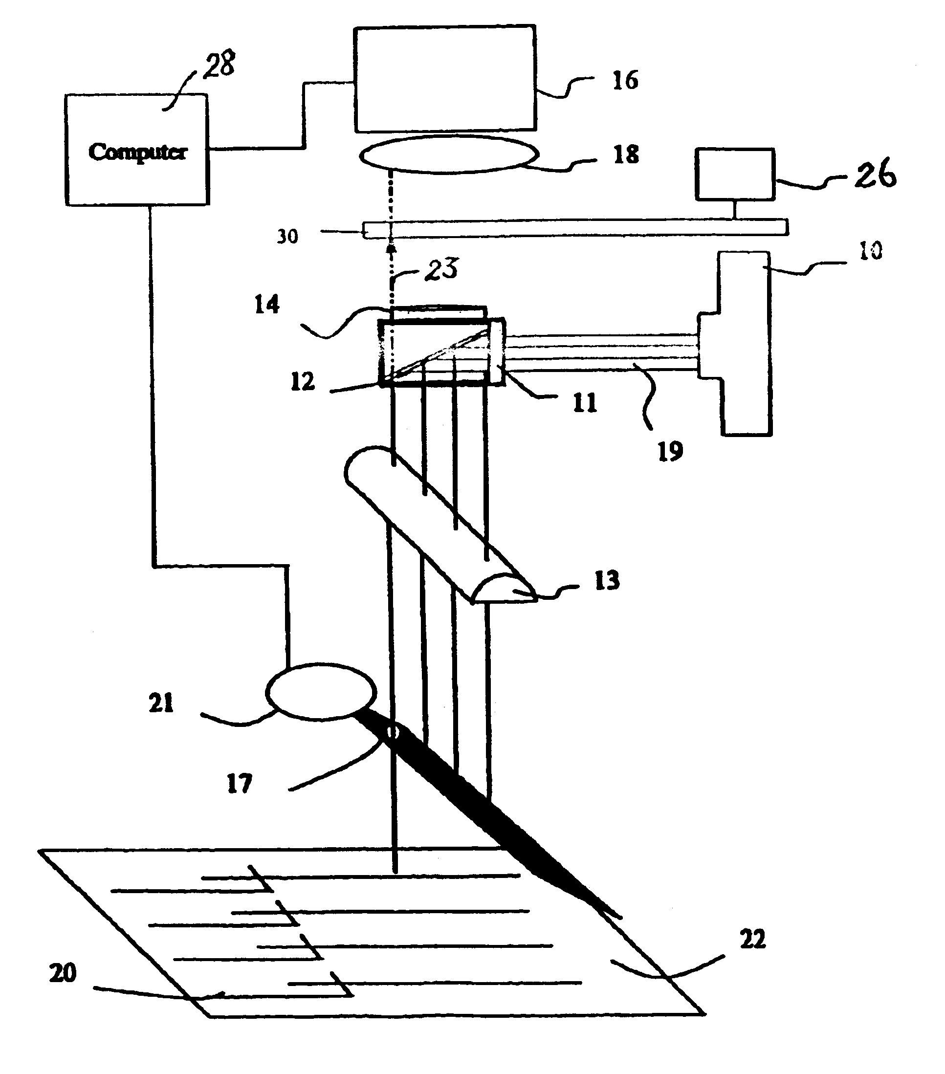
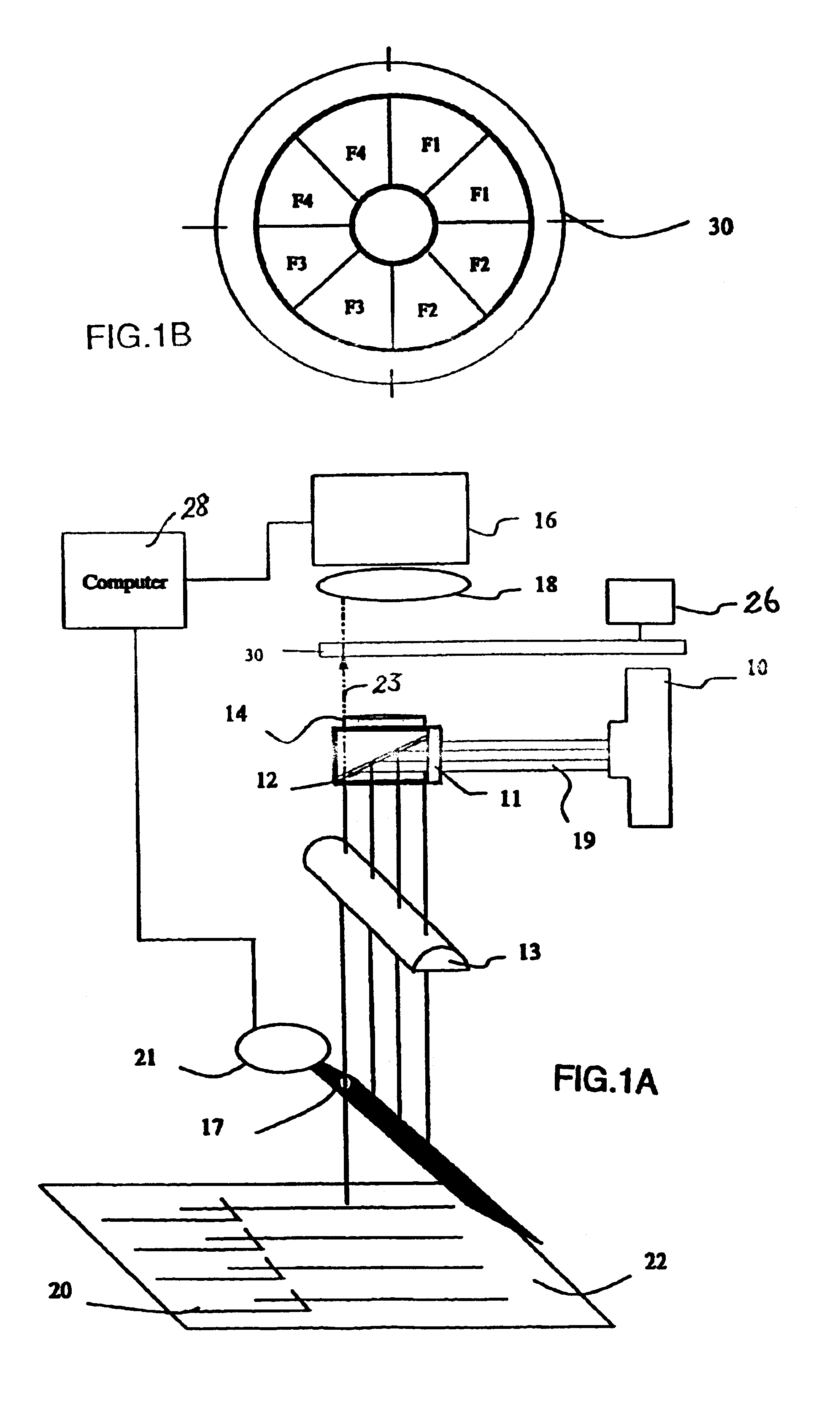
FIG. 1 is a general schematic illustration of the multichannel epifluorescent detection system using a moving pinhole. The system includes a radiation source 10, an interference filter 11, a dichroic beamsplitter 12, a convergent cylindrical rectangular lens 13, a long pass filter 14 and a photon detector 16. The source irradiates excitation light 19 to the dichroic beamsplitter 12 which is positioned at an angle (which is 45.degree.0 in this example) to the beam. This beamsplitter reflects radiation of wavelengths below the specified wavelength, acting as a long pass filter The reflected radiation is then directed axially to the sample channels 20. An interference filter 11 is preferably included in this embodiment to isolate the wavelength necessary for excitation of the fluorescent sample and at the same time eliminate the background scatter caused by the radiation of undesired wavelengths. The interference filter 11 is particularly essential to isolate the necessary excitation w...


PUM


Abstract

An optical detection system comprising an electromagnetic radiation source, a source radiation focusing and collimating means, a photodetector, an emitted radiation focusing means and a source radiation blocking panel. The radiation source is used to direct source radiation onto a sample which is disposed in a sample platform. The source radiation focusing and collimating means is disposed between the radiation source and the sample for focusing and collimating the source radiation onto the sample. The photodetector is adapted for receiving radiation emitted from the sample which has been focused by the emitted radiation focusing means. The source radiation blocking panel, disposed between the source radiation focusing and collimating means and the sample, is unique in that it is capable of reducing light scattering and interference, such that a clear signal from each individual sample can be obtained by the photodetector.

Description

The present invention is related to optical detection systems. In particular, the present invention is related to optical detection systems which can analyze multiple samples simultaneously.On many occasions, in chemistry and biology, large numbers of samples need to be analyzed. Particularly in molecular biology, in the Human Genome Project, high speed analyses with high throughput are necessary to achieve the goals of the project. Genetic mapping and DNA sequencing on slab gels are currently performed by using automated DNA sequencing with mono-colour or multi-color fluorescent dye labeling. Because capillary electrophoresis (CE) and particularly CE combined with laser induced fluorescence (CE-LIF) offers rapid charged species analyte separation and high detection sensitivity, it is particularly attractive as a separation technique in DNA sequencing applications. However, the number of capillaries that can be analyzed at one time limits the total throughput of the analysis. To inc...

Claims


Application Information

Patent Timeline
IPC IPC(8): G01N27/447
CPCG01N27/44721G01N27/44782
Inventor LI, SAM FONG YAU
Owner CE RESOURCES
Why Eureka
Try Eureka