Method for preparing low-resistant p-type SrTiO3

a p-type srtio.sub.3 and low-resistance technology, applied in the field of preparing low-resistance p-type srtio3., can solve the problems of obstructing the preparation of a p-type srtio.sub.3 with desirably lowered resistance, oxygen deficiency serving as a donor, and increasing the activation rate of acceptors, reducing the concentration

Inactive Publication Date: 2004-09-14
JAPAN SCI & TECH CORP
View PDF0 Cites 1 Cited by
  • Summary
  • Abstract
  • Description
  • Claims
  • Application Information

AI Technical Summary

Benefits of technology

According to a second aspect of the present invention, there is provided a method for preparing a low-resistance p-type SrTiO.sub.3, wherein an acceptor (A) and a donor (D) are co-doped into a perovskite-type transition-metal oxide SrTiO.sub.3 during crystal growth to form an impurity complex (A-D-A) of the acceptor and the donor through a crystal growth method in a thermal nonequilibrium state, whereby an impurity formation energy is reduced by less than that in a method of doping the acceptor by itself, so as to provide an increased concentration of the acceptor.
According to a third aspect of the present invention, there is provided a method for preparing a low-resistance p-type SrTiO.sub.3, wherein an acceptor (A) and a donor (D) are co-doped into a perovskite-type transition-metal oxide SrTiO.sub.3 during crystal growth to form an impurity complex (A-D-A) of the acceptor and the donor through a crystal growth method in a thermal nonequilibrium state, whereby a Coulomb scattering mechanism having a long range force is converted into a dipole or multipole scattering mechanism having a short range force, so as to provide an increased mobility of the impurities.
According to a fourth aspect of the present invention, there is provided a method for preparing a low-resistance p-type SrTiO.sub.3, wherein an acceptor (A) and a donor (D) are co-doped into a perovskite-type transition-metal oxide SrTiO.sub.3 during crystal growth to form an impurity complex (A-D-A) of the acceptor and the donor through a crystal growth method in a thermal nonequilibrium state, whereby the acceptor has a shallower impurity level than that in a method of doping N by itself, so as to provide an increased activation rate of the acceptor.
The CVD method promotes crystal growth under hydrogen atmosphere, and a hydrogen donor will remain in the resulting crystal because hydrogen acts as a donor. However, the remaining donor can be removed by subjecting the resulting crystal to annealing (at about 500.degree. C.), and thereby an acceptor acts to provide a desirable low-resistance p-type crystal.
When an impurity complex of acceptors .circle-solid. and donors .circleincircle. is formed by co-doping an n-type dopant of Nb (niobium) and a p-type dopant of N (nitrogen) at a ratio of 1:(1+x) where 0<x<100, respective wave functions of the acceptors and the donors are hybridized as shown in FIG. 2. Thus, the co-doping allows the acceptors to have a shallower impurity level than the deep impurity level provided by the conventional method of doping N by itself (hereinafter referred to as "independent doping method"), so that an activation rate of the acceptors is increased.
Further, an impurity formation energy can be reduced by less than that in the independent doping, to provide an increased concentration (solid solubility limit) of the acceptors. In addtion, a Coulomb scattering mechanism having a long range force can be converted into a dipole or multipole scattering mechanism having a short range force to provide an about double-digit-increased mobility of the impurities.

Problems solved by technology

On the other hand, it has been difficult to prepare a p-type SrTiO.sub.3 having a desirably lowered resistance even by adopting any conventional technologies.
Further, the doping of N as an acceptor causes a compensation effect, which inevitably leads to oxygen deficiency serving as a donor.
Such negative factors obstruct to achieve a desired low-resistance p-type SrTiO.sub.3.

Method used


Image

  • Method for preparing low-resistant p-type SrTiO3
  • Method for preparing low-resistant p-type SrTiO3
  • Method for preparing low-resistant p-type SrTiO3

Examples


first example

Crystal Growth Through MBE Method

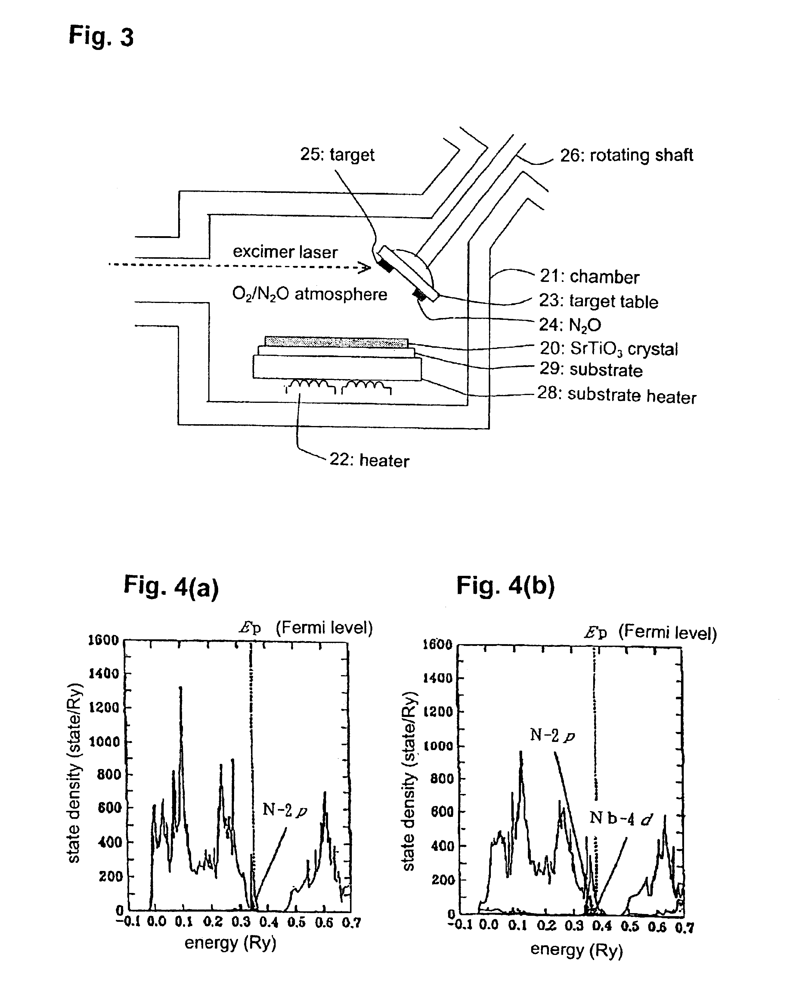
FIG. 3 is a schematic vertical sectional view of a laser-MBE crystal-growth apparatus used in this example. A substrate 29 made of Si was housed in a chamber 21 with placing on a substrate heater 28 heated by a heater 22. A target 25 formed by sintering Sr oxide / Ti oxide in the form of a pellet was fixedly disposed on a target table 23 fixed to the end of a rotating shaft 26 to be rotated by a rotational drive unit outside the chamber 21. A N.sub.2 O 24 as a dopant was fixedly disposed at a N.sub.2 O gas source position of the target table 23. A excimer laser was irradiated from the outside of the chamber 21 onto the target 25 and the N.sub.2 O 24 to introduce abrasion in them, and an n-type dopant of metal Nb (Nb oxide was used as the target) and a p-type dopant of N was co-doped at a ration of 1:2 while crystal-growing SrTiO.sub.3 on the substrate 29 under oxygen / N.sub.2 O atmosphere.

In order to check up on the effect of the co-doping during the la...

second example

Crystal Growth Through CVD Method

FIG. 5 is a schematic vertical sectional view of a CVD crystal-growth apparatus used in this example. Based on the CVD method, organic metal complexes of Sr, Ti and Nb, i.e. Sr (DPM).sub.2, Ti (DPM).sub.3 and Nb (DPM).sub.4 (DPM: dipivaloymethanato), were reserved in vessels 11, 12 and 13, respectively, and used as starting materials.

Ammonia was used as a starting material of N. Each of the starting materials was discharged from the corresponding vessel by introducing rare gas from a gas inlet 3 into each of the vessels. The starting materials were heated up to a high temperature at a vaporizing chamber 2, and forcibly vaporized. The vapor of the starting materials was introduced in a chamber heated by a heater 7, and directed toward a substrate 9 through a gas nozzle 6 to grow a SrTiO.sub.3 crystal 10 on the substrate 9 heated by a substrate heater 8. During this process, oxygen gas was introduced from a gas inlet 4 into the chamber 1 to prevent oxy...


PUM

PropertyMeasurementUnit
bandgap energyaaaaaaaaaa
carrier concentrationaaaaaaaaaa
temperatureaaaaaaaaaa

Abstract

The present invention provides a method for preparing a novel low-resistance p-type SrTiO3 capable of opening the way for oxide electronics in combination with an already developed low-resistance n-type SrTiO3. The method is characterized in that an acceptor and a donor are co-doped into a perovskite-type transition-metal oxide SrTiO3 during crystal growth.

Description

The present invention relates to a method for reducing the resistance of a perovskite-type transition-metal oxide SrTiO.sub.3.A perovskite-type transition-metal oxide SrTiO.sub.3 has a wide bandgap energy of 3.3 eV. Therefore, SrTiO.sub.3 gets attention as a base material of other perovskite-type transition-metal oxides, a nonlinear resistive element, a ferroelectric material or the like, and a SrTiO.sub.3 film having a high dielectric constant are actively developing.A high dielectric film consisting of SrTiO.sub.3 is typically prepared through a spattering method using a SrTiO.sub.3 sintered body as a target (e.g. Japanese Patent Laid-Open Publication Nos. 6-140385 and 9-153598).On the other hand, it has been difficult to prepare a p-type SrTiO.sub.3 having a desirably lowered resistance even by adopting any conventional technologies. Specifically, a conventional method of doping a p-type dopant N (nitrogen) by itself has been able to increase carrier concentration only up to abou...

Claims


Application Information

Patent Timeline
Patent Type & Authority Patents(United States)
IPC IPC(8): C23C16/40C30B25/02H01G9/20H01L29/02H01L29/24C30B29/32H01L21/203H01L21/205H01L21/8242H01L27/10H01L27/108
CPCC23C16/409C30B25/02H01G9/2027H01L29/24C04B35/47C30B29/32C04B2235/46Y02E10/542C04B2235/3251Y02P70/50
Inventor YOSHIDA, HIROSHIBETSUYAKU, KIYOSHIKAWAI, TOMOJITANAKA, HIDEKAZU
Owner JAPAN SCI & TECH CORP
Why Eureka
Try Eureka