
Highly conductive and stable nonaqueous electrolyte for lithium electrochemical cells

a nonaqueous electrolyte, high-conductive technology, applied in the direction of non-aqueous electrolyte cells, cell components, therapy, etc., can solve the problems of increasing the obvious and severe phenomenon, reducing the discharge capacity, and not necessarily improving the cell performance or discharge capacity. , to achieve the effect of improving the chemical and electrochemical stability of the electrolyte, improving the electrolyte conductivity, and increasing the electrolyte conductivity

Inactive Publication Date: 2005-01-18
WILSON GREATBATCH LTD
View PDF20 Cites 39 Cited by
  • Summary
  • Abstract
  • Description
  • Claims
  • Application Information

AI Technical Summary

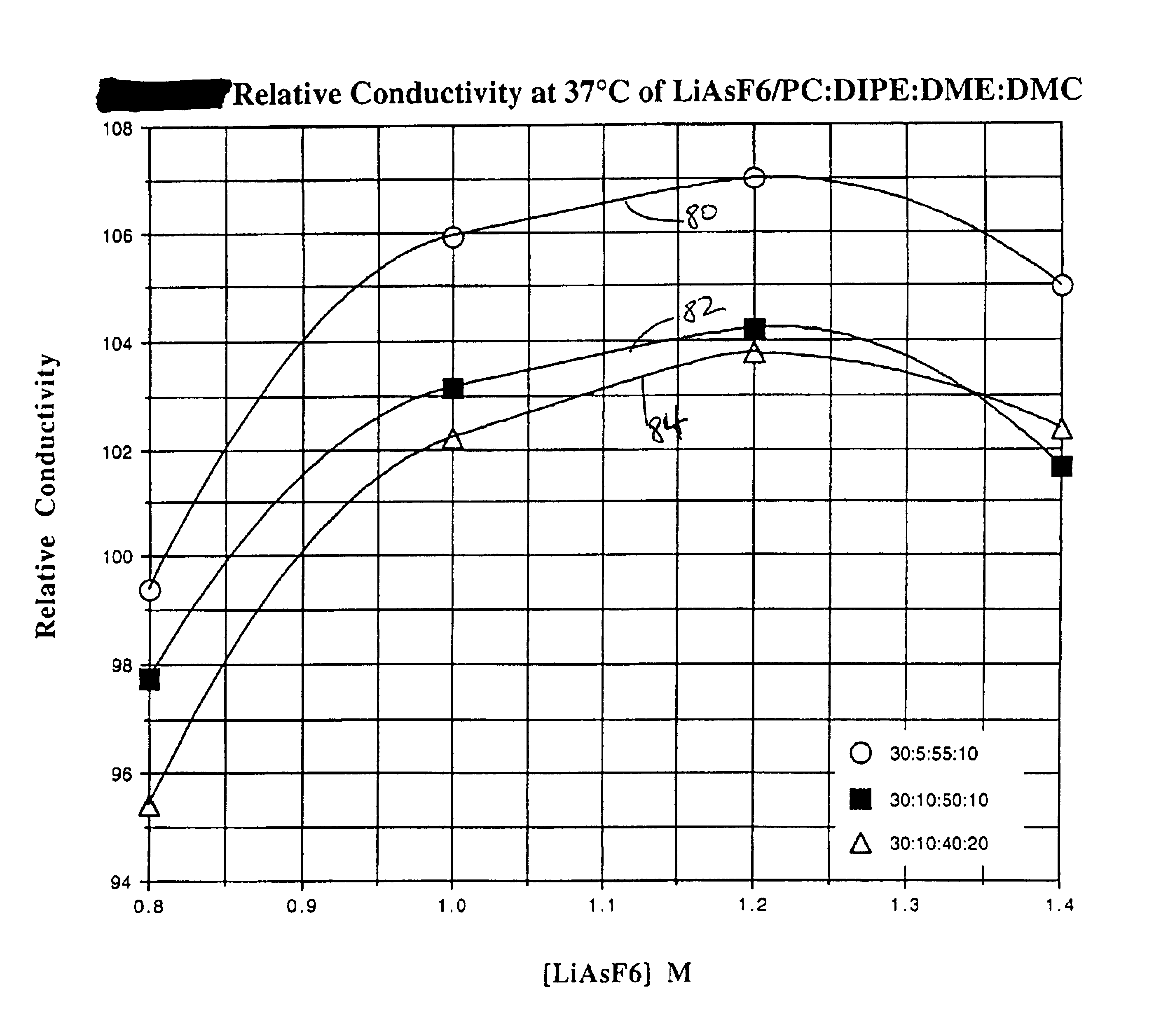
Benefits of technology

In the present invention, the advantage of using DMC (a linear dialkyl carbonate) co-solvent to increase electrolyte conductivity and the advantage of using DIPE (a linear mono-ether) to improve the chemical and electrochemical stability of the electrolyte are combined. Partial replacement of the cyclic carbonate (PC) and linear di-ether (DME) in the conventional electrolyte with linear carbonate (DMC) and linear mono-ether (DIPE) improves electrolyte conductivity significantly. Since both DMC and DIPE have a smaller DN number than that of DME, voltage delay problem is minimized as well. The present electrolytes are useful in all types of primary and secondary lithium or lithium ion cells, in addition to those used to power implantable medical devices. In cardiac defibrillators, pulse voltage drop and voltage delay under high current pulse discharge conditions is minimized in cells activated with the present electrolytes.

Problems solved by technology

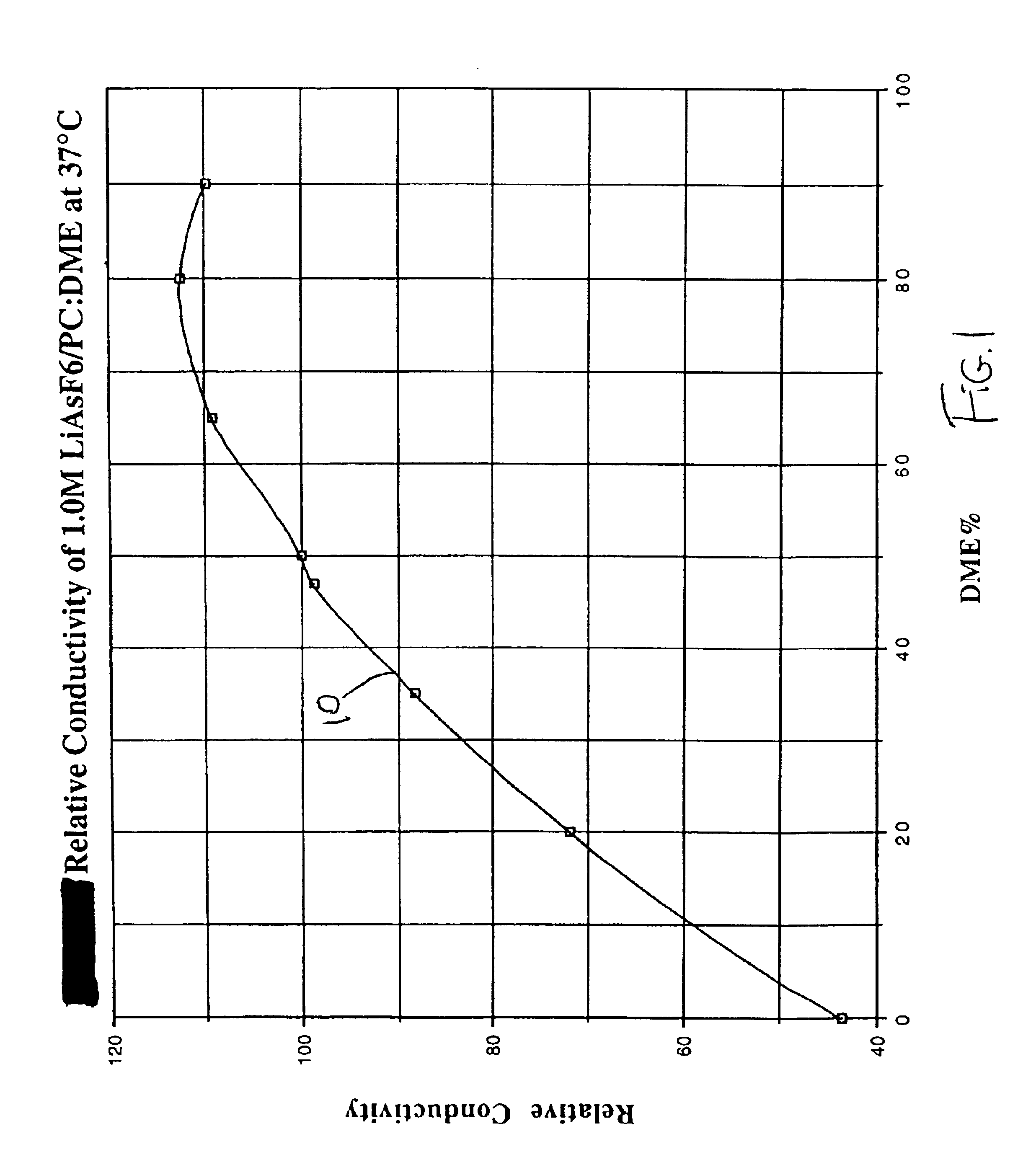
It is interesting to note that the above-discussed electrolyte using a PC / DME solvent system does not provide maximum conductivity at its one-to-one volume ratio.
Therefore, high electrolyte conductivity does not necessarily mean better cell performance or improved discharge capacity.
For longer-term cell storage or usage, this phenomenon becomes more obvious and severe.
However, PC:DME:DMC electrolyte systems have shown instability under certain experimental conditions.
Thus, although this ternary solvent electrolyte is commonly used to activate Li / SVO cells, there are some applications for which it is not useful.

Method used


Image

  • Highly conductive and stable nonaqueous electrolyte for lithium electrochemical cells
  • Highly conductive and stable nonaqueous electrolyte for lithium electrochemical cells
  • Highly conductive and stable nonaqueous electrolyte for lithium electrochemical cells

Examples


example i

PC:DME System, Short Term Test Using a SVO Electrode

Lithium anode material was pressed on a nickel current collector screen and silver vanadium oxide (SVO) cathode material was pressed on a titanium current collector screen. A prismatic cell stack assembly configuration having two layers of microporous membrane polypropylene separator sandwiched between the anode and cathode was prepared. The electrode assembly was then hermetically sealed in a stainless steel casing in a case negative configuration and activated with an electrolyte. Some of the cells in this example were activated with electrolyte 1 (as reference cells) and others were activated with electrolytes 2 and 3.

A constant resistive load of 7.5 kΩ was applied to the cells during an initial pre-discharge period. The pre-discharge period is referred to as burn-in and depleted the cells of approximately 1% of their theoretical capacity. After burn-in and an acceptance pulse train discharge, applying a pulse train every thirty...

example ii

PC:DMC System, Short Term Test Using a SVO Electrode

Hermetically sealed Li / SVO cells were constructed as described in Example 1 and activated with electrolytes 1 and 4, respectively. After burn-in and an acceptance pulse train discharge, applying a pulse train at 37° C. every thirty minutes discharged these cells. The pulse trains consisted of four 10-second pulses (23.2 mA / cm2) with a 15-second rest after each pulse. The delivered capacities expressed as milliampere hours at several voltage limits are listed in Table 2.

TABLE 2Cell Discharge CapacitiesCapacity* (mAh) atLiAsF6Voltage CutoffElectrolyteConc.PC:DME:DMC2.0 V1.7 V1.5 V11.0M50:50:0015081679173541.2M30:00:70141116681735*Average of five cells.

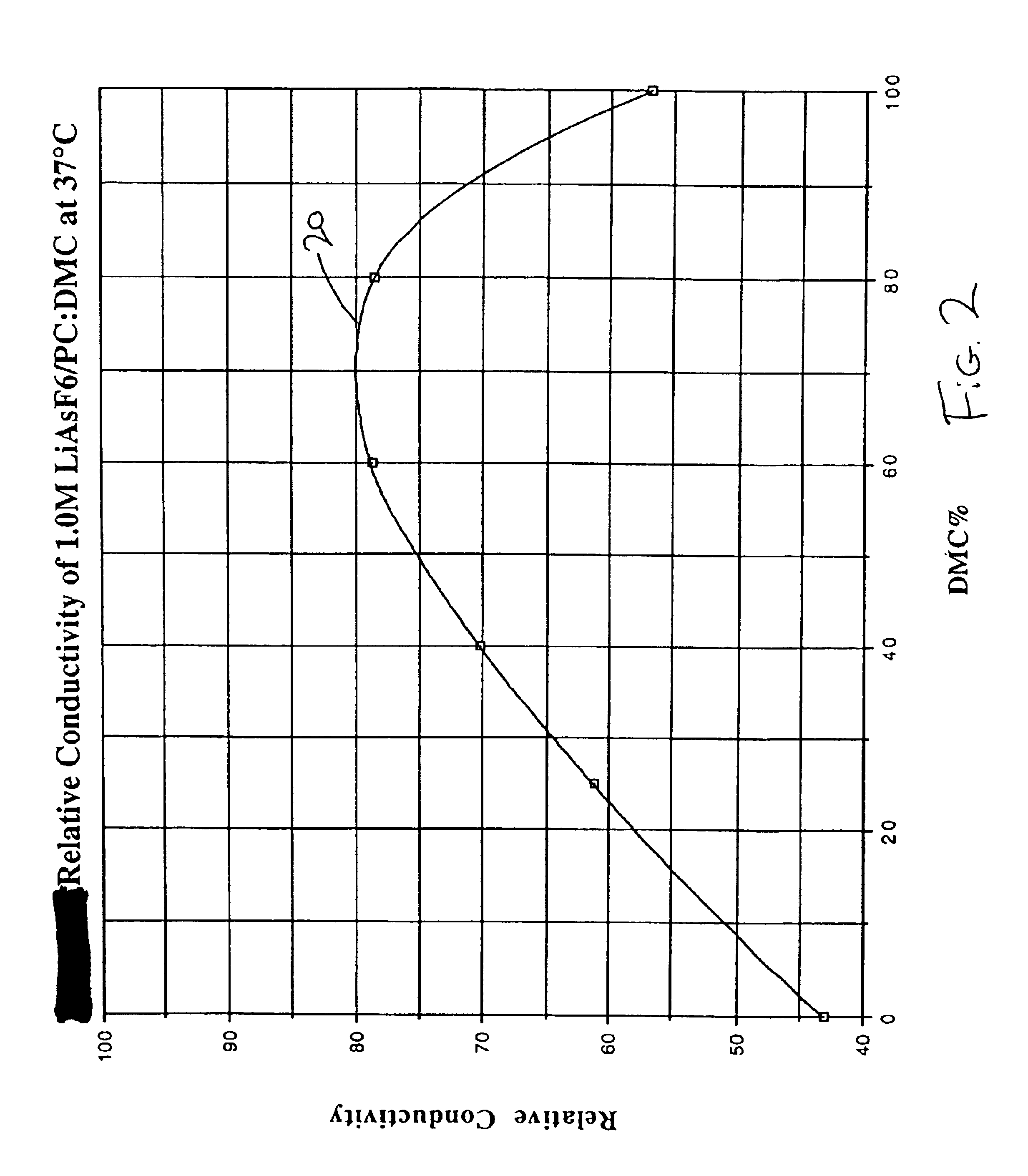
Li / SVO cells containing electrolyte 4 delivered less capacity than the cells activated with electrolyte 1. The relative conductivity of the binary solvent (PC:DMC) electrolyte system is shown by curve 20 in FIG. 2. The results of Examples 1 and 2 demonstrate that the delivered capacity...

example iii

PC:DME System, Long Term Test Using a SVO Electrode

Hermetically sealed Li / SVO cells were constructed as described in Example 1 and activated with electrolytes 1 to 3, respectively. After burn-in and an acceptance pulse train discharge, applying a pulse train at 37° C. every 39 days using a 9.53 K-ohm load discharged these cells. The pulse trains consisted of four 10-second pulses (23.2 mA / cm2) with 15-second rest between each pulse. The results are summarized in Table 3 (PT stands for pulse train).

TABLE 3Long Term Test Pulse Train Data (V)*ElectrolyteP(pre1)V-DelayP(1 min)P(4 min)PT-113.2150.0002.6212.49123.2150.0002.6692.55033.2180.0002.6872.587PT-213.1310.0002.5702.44223.2150.0002.6112.49133.2180.0002.6162.515PT-312.8650.0002.4002.31122.8550.0002.4332.35432.8630.0002.4482.379PT-412.5980.1082.1142.21922.5890.1302.1182.25832.5950.1952.0872.288PT-512.5460.0771.9352.05023.5450.1291.8582.05133.5460.1501.8222.058PT-612.5260.1021.8101.92022.5240.1091.8251.95732.5270.1121.8251.974PT-712.4...


PUM


Abstract

The present invention is directed to at least partially replacing PC and / or DME with a linear carbonate, preferably dimethyl carbonate, and a linear mono-ether, the most preferred being diisopropyl ether, in electrolytes useful for activating alkali metal-containing cells. This electrolyte has improved conductivity and provides electrochemical cells with enhanced discharge performance. A most preferred electrolyte comprises 1,2-dimethoxyethane, propylene carbonate, dimethyl carbonate and diisopropyl ether.

Description

BACKGROUND OF THE INVENTION1. Field of the InventionThis invention generally relates to the conversion of chemical energy to electrical energy. More particularly, the invention relates to both primary and secondary non-aqueous electrolyte lithium-containing electrochemical cells. Such cells are typically used to power implantable medical devices, for example cardiac defibrillators. In particular, the invention relates to a quaternary solvent system including a cyclic carbonate, linear di-ether, linear carbonate and linear mono-ether. The solvent system provides an electrolyte having higher conductivity than conventional solvent electrolytes.2. Prior ArtThe successful production of lithium electrochemical cells and their widespread application are largely dependent on the development of highly conductive and stable non-aqueous organic electrolytes. Non-aqueous organic electrolytes are composed of a salt dissolved in an organic solvent system of either a single solvent or mixed solven...

Claims


Application Information

Patent Timeline
IPC IPC(8): H01M4/50H01M4/58H01M10/08H01M10/06H01M4/54H01M10/40H01M10/36H01M4/48H01M6/14H01M6/16A61N1/39A61N1/378H01M4/131H01M4/133H01M4/485H01M4/505H01M4/52H01M4/525H01M4/587H01M4/62H01M10/0525H01M10/0569
CPCH01M4/131H01M4/485H01M6/164H01M10/0525H01M10/0569H01M4/5815H01M4/133H01M4/505H01M4/525H01M4/54Y02E60/122H01M4/587H01M2300/0042Y02E60/10
Inventor GAN, HONGTAKEUCHI, ESTHER S.
Owner WILSON GREATBATCH LTD
Learn More