Piezoelectric liquid-jet head having a superconductor layer

a liquid-jet head and superconductor layer technology, applied in piezoelectric/electrostrictive/magnetostrictive devices, piezoelectric/electrostriction/magnetostriction machines, etc., can solve the problem of difficult to achieve a high density array of piezoelectric elements, difficult cutting of recording heads, and complex manufacturing processes, etc. problem, to achieve the effect of uniform piezoelectric characteristics of the piezoelectric elemen

Inactive Publication Date: 2005-04-26
SEIKO EPSON CORP
View PDF5 Cites 3 Cited by
  • Summary
  • Abstract
  • Description
  • Claims
  • Application Information

AI Technical Summary

Benefits of technology

[0019]In the second aspect, the crystal plane orientation of the piezoelectric layer is (100)-orientation, so that the piezoelectric characteristics of the piezoelectric element can be enhanced substantially.
[0021]In the third aspect, the crystal plane orientation of the piezoelectric layer is (100)-orientation, so that the piezoelectric characteristics of the piezoelectric element can be enhanced substantially.
[0031]In the eighth aspect, the pressure generating chamber and the piezoelectric element, both of predetermined shapes, can be formed reliably.
[0033]In the ninth aspect, there can be provided a liquid-jet apparatus having the liquid-jet head mounted thereon that can make the piezoelectric characteristics of the piezoelectric element nearly uniform and eject a liquid at maximum output.

Problems solved by technology

However, this recording head needs a difficult step of cutting and dividing the piezoelectric element in a comb tooth shape in conformity with the array pitch of the nozzle orifices, and also requires an operation for aligning and fixing the divisions of the piezoelectric element to the pressure generating chambers.
Consequently, the manufacturing process is complicated.
However, a certain size of the vibration plate is required because of the usage of flexural vibration, thus posing difficulty in achieving a high density array of the piezoelectric elements.
With the above-described ink-jet recording head, for example, a drive voltage is applied from external wiring or the like to the lower electrode and the upper electrode having the piezoelectric layer sandwiched therebetween to generate a predetermined drive electric field in the piezoelectric layer, thereby causing flexural deformation to the piezoelectric element and the vibration plate.
These grain boundaries constitute the cause of hampering the expansion and contraction of the piezoelectric layer, i.e., the expansion and contraction of the columnar crystals.
This poses the problem that ink ejection cannot be performed at maximum output, namely, with maximum amount of displacement of the piezoelectric element when a certain driving electric field is generated in the piezoelectric layer.
Even when the predetermined driving electric field is generated in the piezoelectric layer, the problem arises that under the influence of the grain boundaries, the piezoelectric characteristics of the piezoelectric element substantially fluctuate.
These problems are not limited to the ink-jet recording head, but needless to say, occur similarly in other liquid-jet heads.

Method used


Image

  • Piezoelectric liquid-jet head having a superconductor layer
  • Piezoelectric liquid-jet head having a superconductor layer
  • Piezoelectric liquid-jet head having a superconductor layer

Examples


embodiment 1

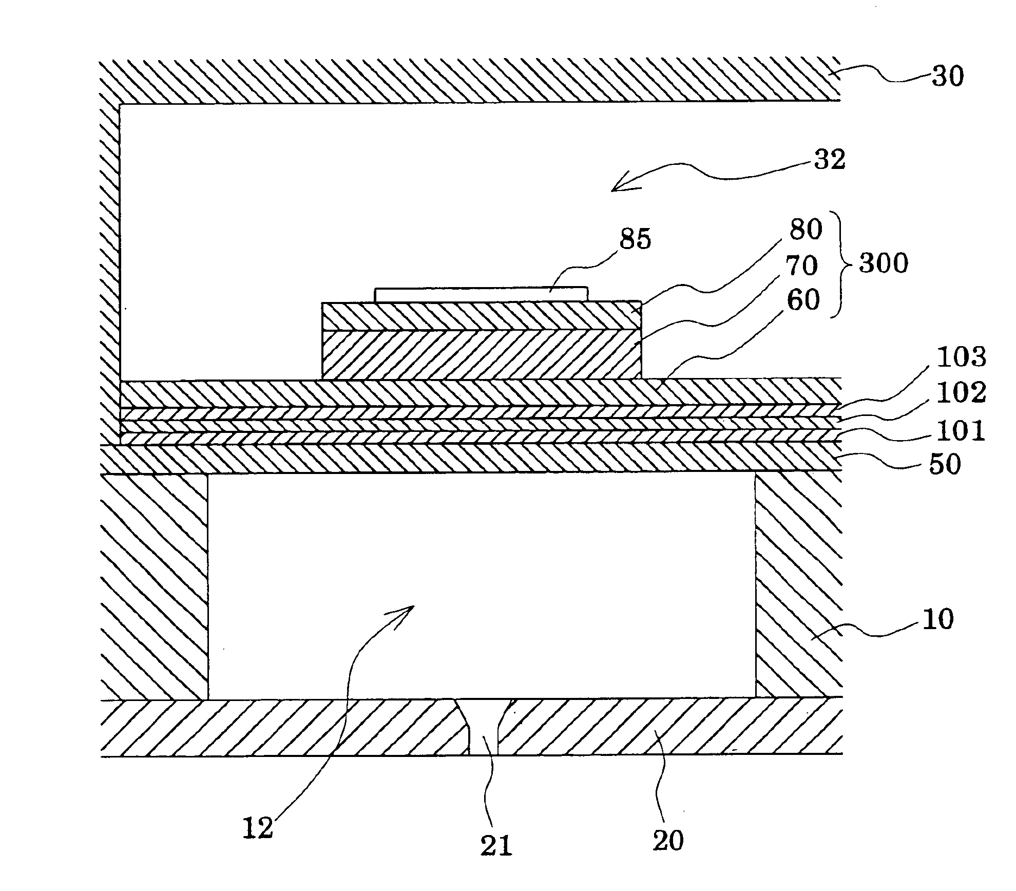
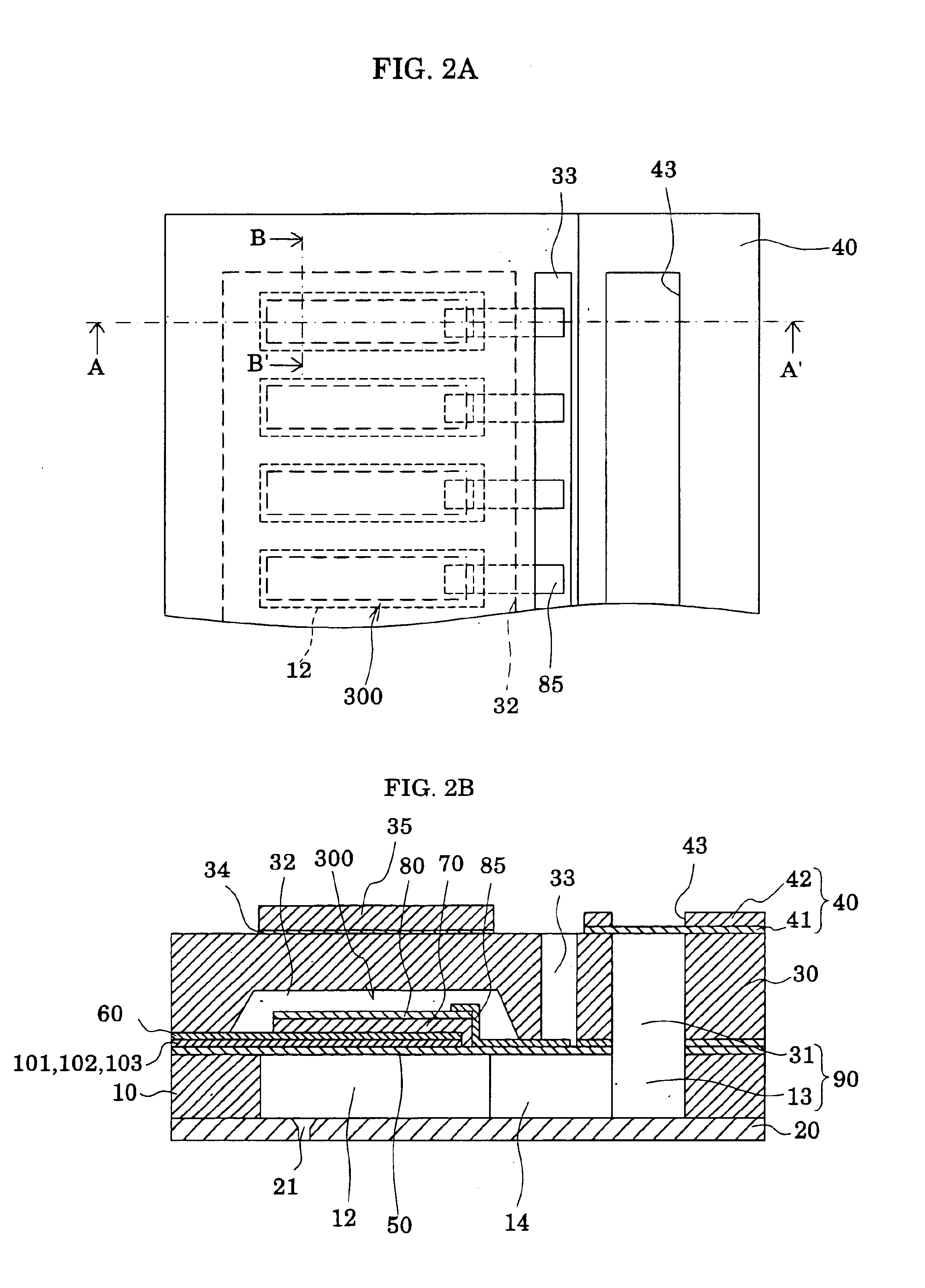
[0046]FIG. 1 is an exploded perspective view showing an outline of the liquid-jet head according to embodiment 1 of the present invention. FIGS. 2A and 2B are, respectively, a plan view of FIG. 1, and a sectional view taken on line A-A′ of FIG. 2A. FIG. 3 is a sectional view taken on line B-B′ of FIG. 2A.

[0047]As shown in the drawings, a passage-forming substrate 10, in the present embodiment, consists of a single crystal silicon substrate having a crystal plane orientation (100). A 1 to 2 μm thick elastic film 50, composed of silicon oxide (SiO2) formed beforehand by thermal oxidation, is formed on one surface of the passage-forming substrate 10.

[0048]In the passage-forming substrate 10, pressure generating chambers 12 divided by a plurality of compartment walls 11 are parallelly provided widthwise by dry etching performed from the one surface of the single crystal silicon substrate. The longitudinal direction of the pressure generating chamber 12 is preferably either the same dire...

example 1

[0069]A zirconium oxide layer composed of yttria stabilized zirconia (YSZ), a cerium oxide layer composed of cerium dioxide (CeO2), a superconductor layer composed of yttrium-barium-copper-oxygen-based material (YBCO) and a lower electrode film composed of strontium ruthenate (SrRuO3) were sequentially stacked on a single crystal silicon substrate by PLD (pulsed laser deposition). On the lower electrode film, a piezoelectric layer composed of lead zirconate titanate (PZT) was deposited by the sol-gel method to prepare a sample for crystal structure analysis in Example 1. The PZT composition of the piezoelectric layer was Pb1.16Zr0.556Ti0.444O3.

[0070]The conditions for film deposition were drying (180° C., 10 min) and degreasing (385° C., 10 min), which were common to the respective layers. Burning subsequent to degreasing was performed under the conditions, 650° C. and 30 min, for the first layer and the second layer. For the other layers (the third and succeeding layers), the condi...


PUM

PropertyMeasurementUnit
thickaaaaaaaaaa
thicknessaaaaaaaaaa
thicknessaaaaaaaaaa

Abstract

A piezoelectric liquid-jet head apparatus, which provides a nearly uniform piezoelectric element and enables ejection of liquid at maximum output, is disclosed. The piezoelectric liquid-jet head has a piezoelectric element 300 provided on one surface of a passage forming substrate 10 via a vibration plate. The piezoelectric liquid jet head includes: a zirconium oxide layer 101 formed on the surface of the passage forming substrate 10; a cerium oxide layer 102 formed on the zirconium oxide layer 101; a superconductor layer 103 formed on the cerium oxide layer 102 and composed of a yttrium-barium-copper-oxygen-based material (YBCO); a lower electrode 60 formed on the superconductor layer 103 and composed of strontium ruthenate; and a piezoelectric layer 70 which is a single crystal epitaxially grown on the lower electrode 60.

Description

BACKGROUND OF THE INVENTION[0001]1. Field of the Invention[0002]This invention relates to a liquid-jet head, and a liquid-jet apparatus, where a portion of a pressure generating chamber communicating with a nozzle orifice for ejecting a liquid is constituted of a vibration plate, a piezoelectric element is formed on the surface of the vibration plate, and the liquid is ejected by displacement of the piezoelectric element.[0003]2. Description of the Prior Art[0004]An example of a liquid-jet apparatus is an ink-jet recording apparatus having an ink-jet recording head equipped with a plurality of pressure generating chambers for generating pressure for ink droplet ejection by a piezoelectric element or a heating element; a common reservoir for supplying ink to the respective pressure generating chambers; and nozzle orifices communicating with the respective pressure generating chambers. This ink-jet recording apparatus applies ejection energy to ink within the pressure generating chamb...

Claims


Application Information

Patent Timeline
Patent Type & Authority Patents(United States)
IPC IPC(8): B41J2/14B41J2/055B41J2/045
CPCB41J2/14233B41J2202/03B41J2002/14241
Inventor XIN-SHAN, LINISHIWAKI, TSUTOMU
Owner SEIKO EPSON CORP
Why Eureka
Try Eureka