

Conductive pattern material and method for forming conductive pattern
a pattern material and pattern technology, applied in the field of pattern material and pattern formation method, can solve the problems of limiting the making of microstructures by conventional metal etching, affecting the quality of conductive patterns, and breaking of thin-line portions during processing
- Summary
- Abstract
- Description
- Claims
- Application Information
AI Technical Summary
Benefits of technology
Problems solved by technology
Method used
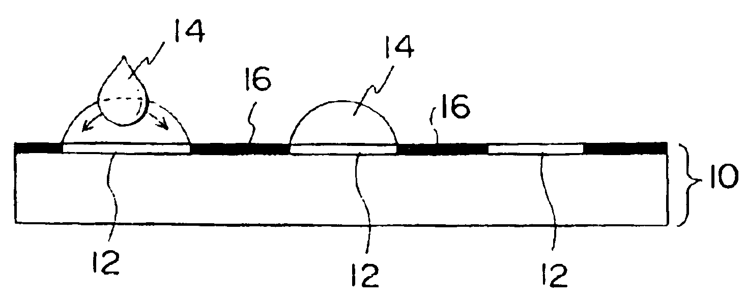
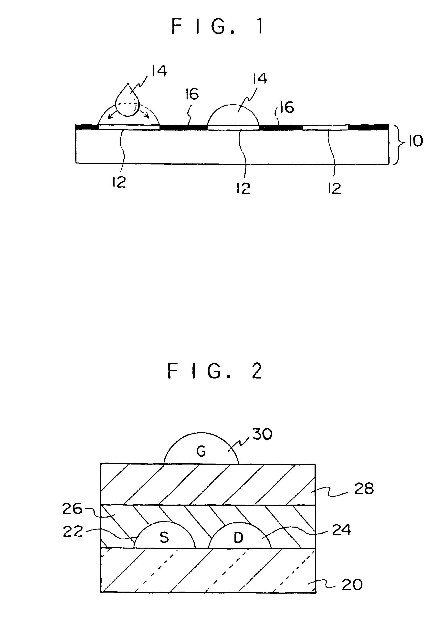
Image

Examples
example 1
Preparation of Conductive Pattern-forming Material:
[0222]On the surface of a polyethylene terephthalate film support having a thickness of 188 μm and subjected to corona treatment, a coating liquid having the following composition was applied by a coating bar (rod #10), and dried at 100° C. for one minute, to prepare an intermediate layer containing an infrared ray absorber having a thickness of 1.6 μm.
Coating Liquid for Intermediate Layer:
[0223]
epoxy resin (Epicoat manufactured by Yuka-Shell Co., Ltd.)2 ginfrared ray absorber (IR125, Wako Pure Chemical)0.2 g1-methoxy-2-propanol9 gmethyl ethyl ketone9 g
[0224]The support surface on which the intermediate layer was formed was subjected to plasma treatment under the following conditions, and a pattern-forming layer was formed by surface graft polymerization.
[0225]The support surface was subjected to plasma treatment using a plasma treatment device (LCVD-01 type manufactured by Shimazu Seisakusho) for 10 seconds in an argon gas atmosphe...
example 2
Preparation of Conductive Pattern-Forming Material:
[0233]A biaxial-oriented polyethylene terephthalate film (A4100 manufactured by Toyobo Co., Ltd.) having a thickness of 188 μm and subjected to corona treatment was subjected to oxygen glowing using a planographic magnetron sputtering device (CFS-10-EP70 manufactured by Shibaura Eletec) under predetermined conditions: initial vacuum 8×10⁸ Pa (9×10⁶ toor); oxygen pressure 9.1×10⁵ Pa (6.8×10³ toor); RF glow 1.5 kw; and processing time 60 seconds.
[0234]Subsequently, a methyl ethyl ketone solution (50 wt %) of the following exemplified monomer (M-3) was applied onto the glowing subjected film, and dried at 100° C. for one minute and irradiated with UV light (a 400-W high-pressure mercury lamp for 30 minutes) to carry out graft polymerization and form a graft layer. Further, 5% by weight of acetonitrile solution of a light-to-heat conversion dye (IR-A) (structure described below) was applied using a rod bar #7 to allow inclusion of the d...
example 3
Preparation of Hydrophilic Pattern:
[0239]The polyethylene terephthalate film subjected to the corona treatment in Example 2, and further subjected to glowing under the same conditions as those of Example 2, was used as a substrate for a support.
[0240]The film was coated with acrylic acid using a rod bar #6 and a coating surface was laminated with a PET film having a thickness of 25 μ. Subsequently, a chromium-deposit mask pattern was placed thereon and irradiated with UV light (a 400-W high-pressure mercury lamp: UVL-400P manufactured by Riko Kagaku Sangyo, irradiation time: 30 seconds). After irradiation with light, the mask and the laminated film were removed and the substrate surface was rinsed with water. As a result, a hydrophilic pattern 3 having polyacrylate grafted in a patterned manner was obtained.
Formation of Conductive Material Layer:
[0241]3 g of bis(1,1-trimethylammonium decanoylaminoethyl)disulfide was added to 50 ml of ethanol solution of silver perchlorate (5 mM), an...
PUM
| Property | Measurement | Unit |
|---|---|---|
| Electrical conductivity | aaaaa | aaaaa |
| Electrical conductor | aaaaa | aaaaa |
| Energy | aaaaa | aaaaa |
Abstract
Description
Claims
Application Information