Method for cleaning hollow tubing and fibers

a hollow tubing and fiber cleaning technology, applied in the direction of cleaning using liquids, detergent compounding agents, dental surgery, etc., can solve the problems of difficult cleaning and maintenance in a clean condition, difficult to clean the surface, difficult to clean the interior surface of passageways, etc., to achieve superior results, reduce the loss of albumin, and increase the number of re-uses

Inactive Publication Date: 2005-09-20
NOVAFLUX INC
View PDF35 Cites 25 Cited by
  • Summary
  • Abstract
  • Description
  • Claims
  • Application Information

AI Technical Summary

Benefits of technology

[0029]We have found a method of cleaning and sterilizing hollow fiber membrane modules such as hemodialyzers, hemofilters and piping systems with high length to width ratio. The lumen, the membrane, the pore structure and the surface of the membranes and piping interiors are cleaned by pressurizing a cleaning agent of a preferred composition to infiltrate the cleaning solution into the lumen of the fibers, while injecting a gas at high velocity into the blood-lumen side so that a two phase flow, of a known liquid to gas ratio, is formed inside the hollow fibers or tubing. This combination of backflushing and two-phase flow loosens materials that have deposited on the lumen and in the pores of the hollow fibers, so that they can be readily flushed away.
[0030]In some types of dialyzers and hollow fiber modules, a premixed two phase flow having a known liquid to gas ratio is passed into the fiber lumen to remove protein deposits, blood clots and debris from the dialyzer or membrane module. The formation and delivery of this two phase flow depends on the membrane type, module geometry and characteristics of the piping system to be cleaned. Biofilm and debris can be readily removed from pipe interiors using this same method.
[0031]The present invention provides methods, compositions and devices for cleaning and sterilizing hemodialyzers that overcome existing inadequacies. The present method can clean all parts of a dialyzer, including fiber lumen, pore structure, and under the cap regions, and addresses the differential fouling of the dialyzer in the venous and arterial sides. The present method delivers both cleaning and sterilization of the dialyzer, increases significantly the number of re-uses, up to forty or more times. The present method also clears middle solutes, such as beta-2M, while minimizing the loss of albumin in patients over a large number of re-uses. Thus used dialyzers cleaned by the method and compositions of this invention approximate a new one in being able to deliver a like-new dialysis dose for each re-use. Cleaning of piping systems having a high l / d according to this invention achieves superior results compared to liquid flushing with considerable saving in reagents and cleaning times.

Problems solved by technology

Interior surfaces of passageways, particularly small-bore or capillary tubing, as well as larger diameter pipes, ducts and the like, which may carry liquids, gases, or slurries, are very difficult to clean and to maintain in a clean condition.
When the flow path is long and narrow, and more specifically when the length to diameter (l / d) is large, it is difficult to clean the surfaces by conventional liquid phase flushing, because such a long, narrow passageways limit liquid flow velocities by creating a high resistance to flow.
As a result of such high l / d and other geometrical limitations, particularly in the case of small diameter tubing, shear stresses that could aid in the removal of contaminants from such tubing surfaces are limited.
Low flow velocities also limit the usefulness of aqueous liquid cleaning solutions and solvents for the same reasons.
Cleaning of small diameter passageways is also difficult because of the nature, adhesion characteristics and solubility of certain types of residues.
This biofilm must be periodically removed because biofilm is the main cause of high bacterial counts and high levels of endotoxins.
In other situations, when an organic layer strongly adheres to the surface of pipes, tubing or other passageways, similar challenges are presented with respect to removal as in the biofilm case.
However, removing biofilm, particles and other undesirable substances from capillary size fluid passageways is quite difficult.
Thus these treatments are only partially and temporarily effective, and the original levels of bacteria return rapidly, sometimes within hours.
The spray may be generated by an aerosol can or an atomizing device, but it does not ensure complete cleaning of adherent debris either.
They are difficult to clean.
The adhesive strength of such blood components to dialyzer surfaces is high, and cannot normally be removed with conventional exposure to liquids alone.
The difficulty of removing these substances from the dialyzer depends on the chemistry of the reagents used for dialyzer cleaning.
Further, blood clots accumulate in the dialyzer over several cleaning cycles.
Blood clots under the cap regions of a dialyzer are changed to solid, gritty substances that are almost impossible to remove, even with manual scrubbing.
Because it is difficult to maintain a high TCV level and retain the pore size distribution in a re-used dialyzer at about the same level as a new one, only about 10-15 re-processings, and often fewer, can be carried out prior to failure, when the dialyzer must be discarded.
Blood clots that form inside the hollow fibers clog some of them, reducing the TCV; also blood clots form particularly in regions under the cap of the dialyzer.
Protein layers also form on the lumen of hollow fibers which can hamper the removal of undesirable solutes from the patient's blood to the dialysate or liquid side.
Precipitation of proteins and other molecules within the pore structure also clog the pores.
Thus reprocessing or cleaning of the dialyzers is very important but has not been sufficiently addressed.
However, this solution, although it sterilizes the hemodialyzer, does not clean the pores by removing proteins, blood clots and the like, and does not clean under the cap regions adequately, where blood clots and other material tends to aggregate.
Thus the dialyzers become fouled, limiting their number of re-uses, compromising dialysis treatment of patients, and raising the cost of dialysis because new dialyzers must be provided more frequently.
Although in principle this method should clean the pores, it is not effective to remove blood clots from the fiber lumen or from the under the cap regions of the dialyzer.
Further, bleach increases the pore size and effects a shift in the pore size distribution in the membrane layer, leading to high loss of albumin in patients.
This has been found to be the main cause of albumin loss in hemodialysis patients, which has an adverse effect on their health.
However, despite some improvements in dialyzer materials, albumin loss in patients remains a major issue with respect to the number of possible re-uses.
Further, the bleach solution method is not efficient in maintaining the TCV above the 80% level of that of a new dialyzer, and maintaining the dialyzer in good functional condition for many re-uses.
However, due to the low pH of citric acid solutions, protein layers deposited on the lumen surface of hollow fibers precipitate inside the pore structure of the membrane layer and are not removed by this processing method.
The method does not adequately clean, and the prolonged elevated temperatures of disinfection leads to shell fatigue.
Thus inadequate cleaning and the cost of energy to sterilize the dialyzer are major drawbacks to this method.
Existing dialyzer reprocessing methods cannot achieve the desired clearance of beta-2M and other undesirable molecules because of the loww of pore volume due to precipitated proteins in the pore structure and by masking the polymer surface of the dialyzer fibers with a protein layer, that diminishes removal of such molecules by adsorption.
Another major limitation in existing reprocessing methods lies in their inability to equally clean both venous and arterial sides of the dialyzers.
This differential fouling problem is caused by the fact that the dialyzer is mounted in one direction during dialysis treatment.
This results in more severe fouling of the hollow fiber lumen and pore structure on the venous side.
None of the current reprocessing methods addresses this major problem.
Another objectionable feature of present-day dialyzer cleaning, is the potential exposure of dialyzer reprocessing workers to infection and other consequences, since the cleaning operation often involves opening the dialyzer caps to manually remove blood clots from under the cap.
The present methods do not clean the dialyzer of protein deposits or other residues, and thus are deficient in that the required treatment function is not delivered to the patient, and the costs of treatment are increased.
Other suggestions for cleaning have been made, but they have proven to be no more effective in cleaning, and some have other problems as well.

Method used


Image

  • Method for cleaning hollow tubing and fibers
  • Method for cleaning hollow tubing and fibers
  • Method for cleaning hollow tubing and fibers

Examples


example 1

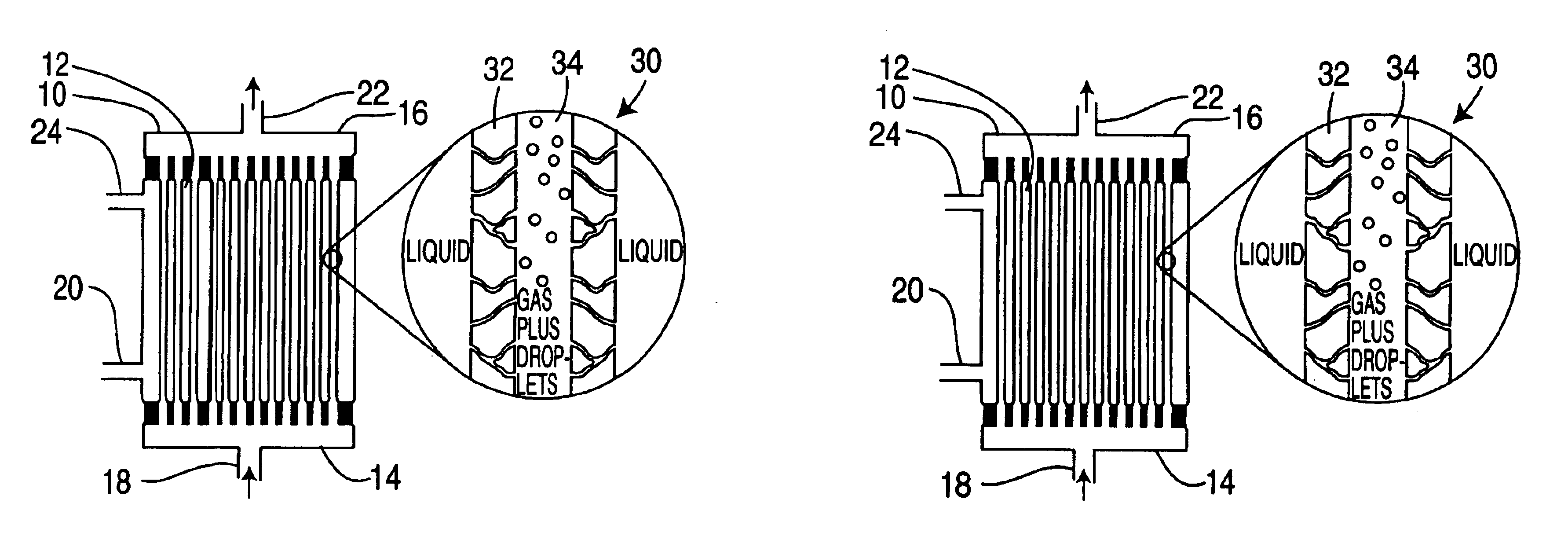
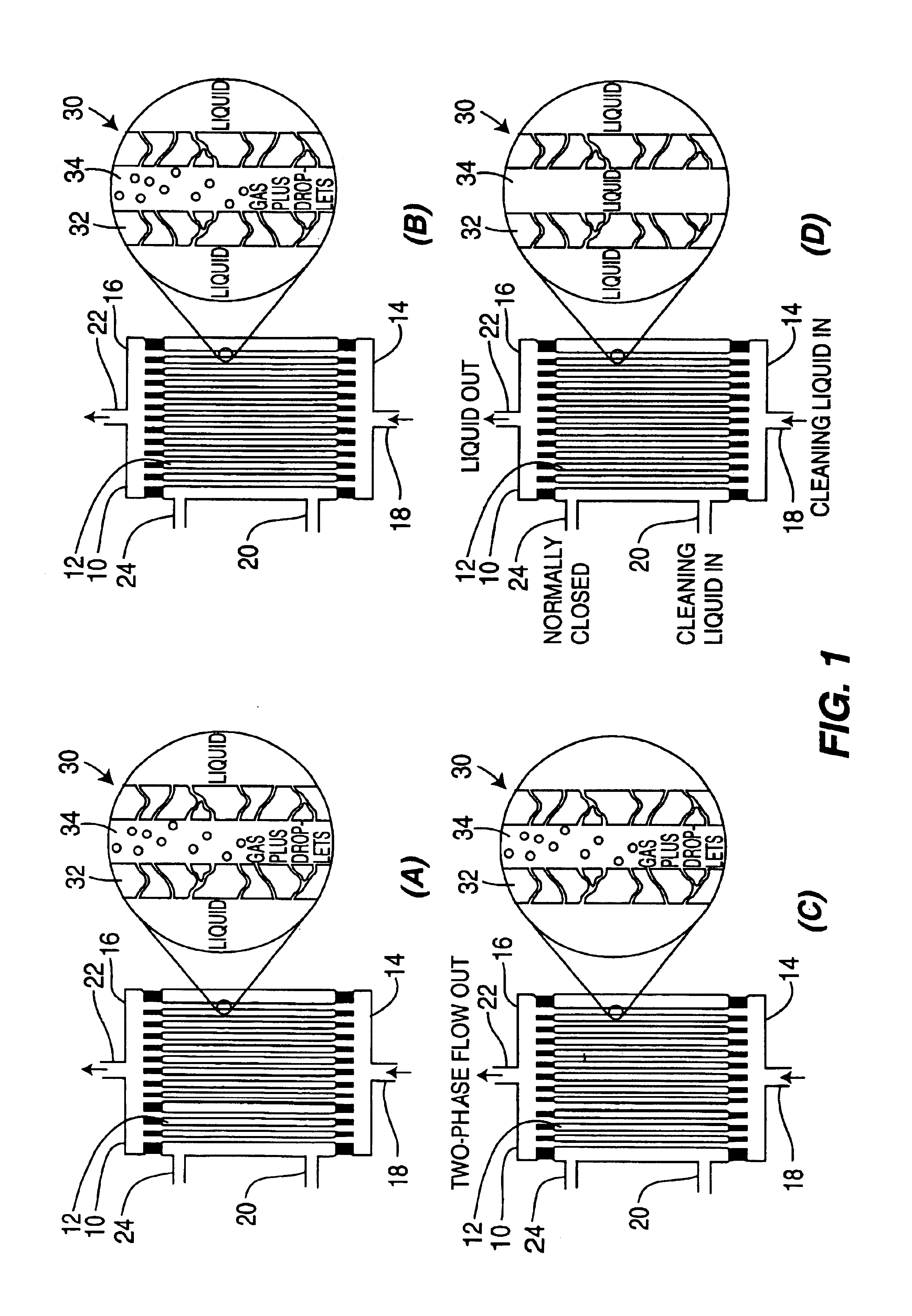
[0078]Eight dialyzers (F80A) made by the Fresenius Co. of Bad Homburg, Germany, were cleaned using a method of the invention. The internal diameter of a hollow fiber was 0.2 mm and the length to diameter ratio of each fiber was 1100. A bundle of 15,000 parallel, hollow fibers made of polysulfone , or a derivative thereof, was used. A cleaning agent of 0.225% sodium hypochlorite (NaOCl) and 200 ppm Cremophor EL nonionic surfactant, a castor oil ethoxylate, having a pH of 11.3, was passed into the dialysate side of the dialyzers and mixed with air delivered from the blood / lumen side of the dialyzers to form a mixed phase flow mixture in situ inside the hollow fibers. Cleaning was carried on for 7 minutes, following by rinsing with water, filling with Renalin® and storing for at least 13 hours prior to re-use. The dialyzer was cleaned and reprocessed after each dialysis session.

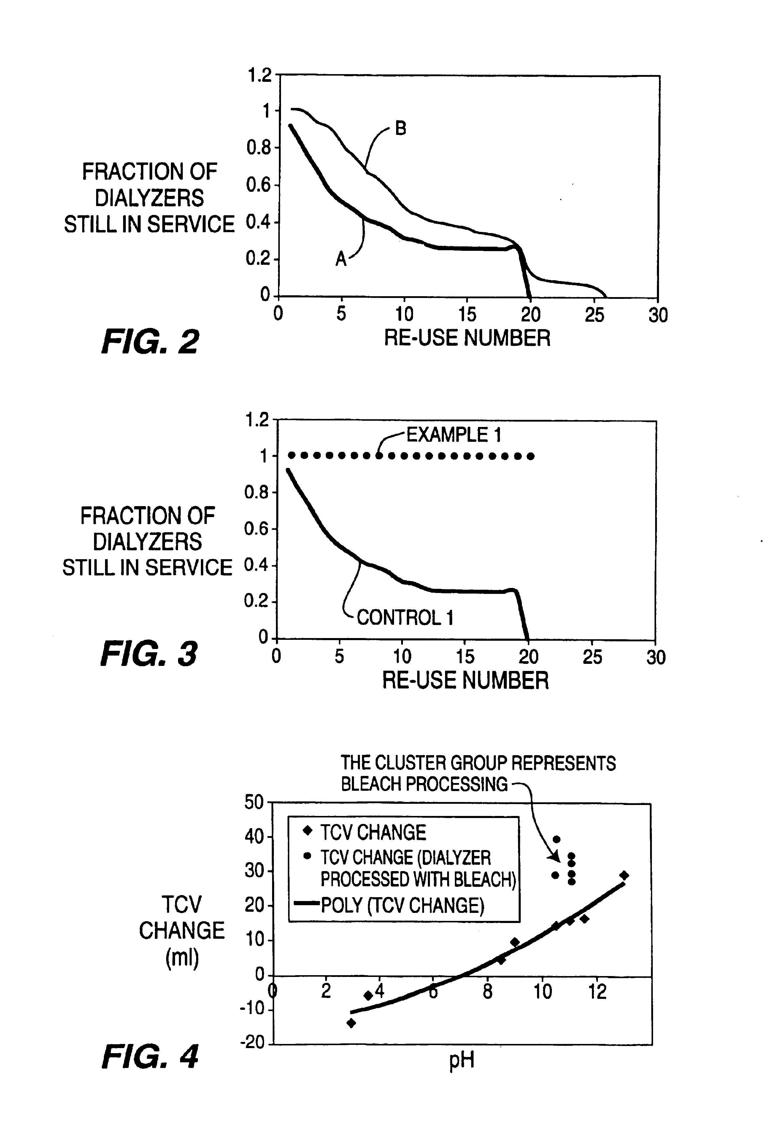
[0079]This cleaning method was continued for 22 re-uses. The TCV was measured after each reprocessing to ensu...

example 2

[0081]The method of Example 1 was repeated using a cleaning solution of sodium hydroxide (pH 12.6) for 7 minutes on a re-used dialyzer which had a TCV of only 66 ml, except that the solution he was pumped into the dialysate side for 2 minutes and air added from the other side. The alternate side sequence was continued for 5 minutes.

[0082]The calculated Reynolds number of flow in the hollow fibers was about 200, based on the known flow rate and the cross-sectional area of air flow, the fiber diameter and the air viscosity.

[0083]The hemodialyzer was rinsed with water. The TCV was 105 ml, an improvement of 59%. It is believed this improvement was due to the efficient removal of proteins, blood cells and components from the lumens. There was no visible blood or hard protein deposits in the header under the cap regions.

[0084]After rinsing, Renalin® was added as a disinfectant.

[0085]An additional 16 dialyzers were processed as above. The average improvement was 21.1±13.6 ml, or an improve...

example 3

[0087]The method of Example 2 was repeated on a failed hemodialyzer sterilized with Renalin® using as the cleaning solution 0.225% of NaOCl and 200 ppm of a surfactant, Cremophor EL, having a pH of 11.3, for a total cycle of 7 minutes.

[0088]The TCV was 104 ml, an improvement of 45 ml, or 76% increase in TCV.

[0089]Eighteen additional failed hemodialyzers were processed as above. A 29% improvement was obtained, 90% of these failed dialyzers were now usable, with a TCV above the 80% level as required by the FDA.


PUM

PropertyMeasurementUnit
temperatureaaaaaaaaaa
velocityaaaaaaaaaa
diameteraaaaaaaaaa

Abstract

Hollow porous fibers containing adhered contaminants are cleaned to remove the contaminants by backflushing a liquid to fill the pores, and adding a flow of gas so as to form a two-phase mixture of gas and bubbles of liquid that can scrub the fibers, loosening the contaminants and allowing them to be flushed from the hollow fibers. The method is particularly useful for cleaning hemodialyzers used for dialysis and hollow fiber modules used in water treatment and separations. The two phase flow method is specifically effective in cleaning piping systems having high length to diameter (l / d) ratios.

Description

[0001]This invention is a continuation-in-part of application Ser. No. 09 / 466,714 filed Dec. 17, 1999, now U.S. Pat. No. 6,454,871 which is a continuation-in-part of Ser. No. 08 / 880,662 filed Jun. 23, 1997, now U.S. Pat. No. 6,027,572.[0002]This invention relates to a method for removing biofilm, debris, contaminants and the like from the surfaces of hollow passageways, including passageways which have irregular or complex shapes, or whose walls are permeable, using a water-based cleaning mixture.BACKGROUND OF THE INVENTION[0003]Interior surfaces of passageways, particularly small-bore or capillary tubing, as well as larger diameter pipes, ducts and the like, which may carry liquids, gases, or slurries, are very difficult to clean and to maintain in a clean condition. When the flow path is long and narrow, and more specifically when the length to diameter (l / d) is large, it is difficult to clean the surfaces by conventional liquid phase flushing, because such a long, narrow passagew...

Claims


Application Information

Patent Timeline
Patent Type & Authority Patents(United States)
IPC IPC(8): A61L2/22A61C1/00A61L2/18A61M1/16B01D65/06B01D65/02B01D65/00B08B9/02C23G5/00C11D11/00C11D3/02C11D3/14C11D3/39C11D3/395C11D3/48B08B9/032
CPCA61C1/0076A61L2/186A61L2/22A61M1/169B01D65/02B01D65/022B08B9/0326B08B9/0327C11D3/044C11D3/14C11D3/3947C11D3/3956C11D3/48C11D11/0041C23G5/00A61M1/1682B01D2321/04B01D2321/164B01D2321/185B08B2209/022
Inventor TABANI, YACOOBLABIB, MOHAMED EMAM
Owner NOVAFLUX INC
Why Eureka
Try Eureka