Both have some margin of error due to the inherent inaccuracies of the fabrication techniques.
If inaccuracies introduce errors in either (or both)
pitch or size that are too large, then the fibers can be inserted at an angle or will not be positioned correctly in the ferrule.
In either case, this negatively affects the ability to couple light efficiently, if at all, from one bundle to another or from an optical or opto-
electronic component to a
fiber bundle.
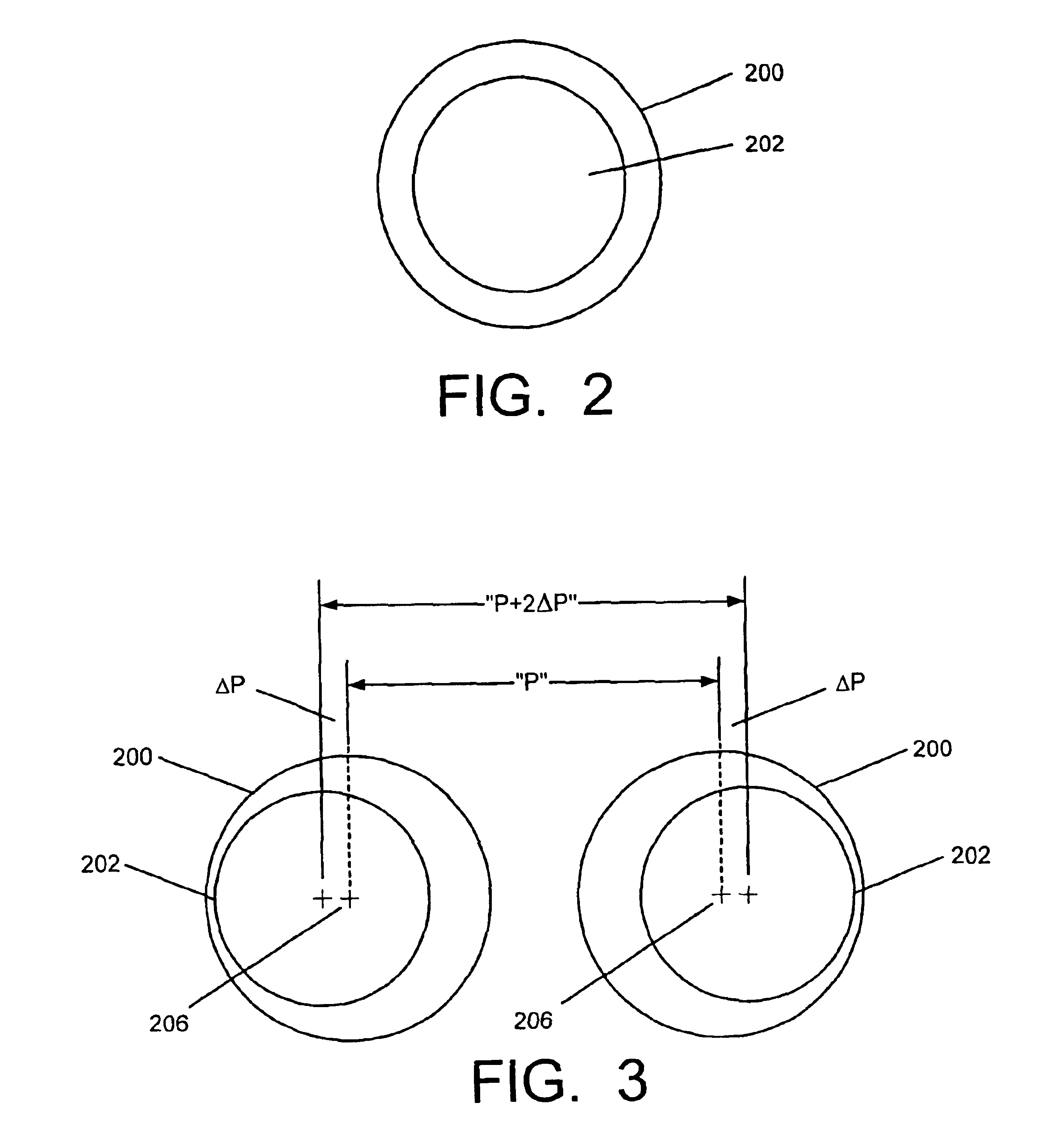
If the hole
pitch is inaccurate, then fibers from one bundle will not line up well with fibers of another bundle.
However, even if the center-to-center
pitch of the holes is very accurate, because the hole
diameter is larger than the fiber (and each hole likely varies across an array) each fiber need not be in the exact same place in the hole as the other fibers in their holes, then that can cause misalignment, leading to inefficiencies or unacceptable losses.
While this may be acceptable for multi-mode fibers, for single mode fibers this would be a huge offset that could make connections unacceptable or impossible.
Nevertheless, in actuality, the ferrule hole 200 must be larger than the fiber 202 by enough of a margin to allow for easy
insertion—ultra-tight tolerances can not be effectively used.
Plastic molding technology is very process sensitive and molds having the requisite precision are extremely difficult to make.
Even so, yields tend to be poor due to the inherent manufacturing process errors that occur in plastics molding.
Since the tolerances on these pieces must be very accurate (on the order of about 1 to 2 micrometers), high yield manufacture is difficult.
As a result, the cost of terminating fiber bundles into these connectors can be quite expensive, running hundreds of dollars per side.
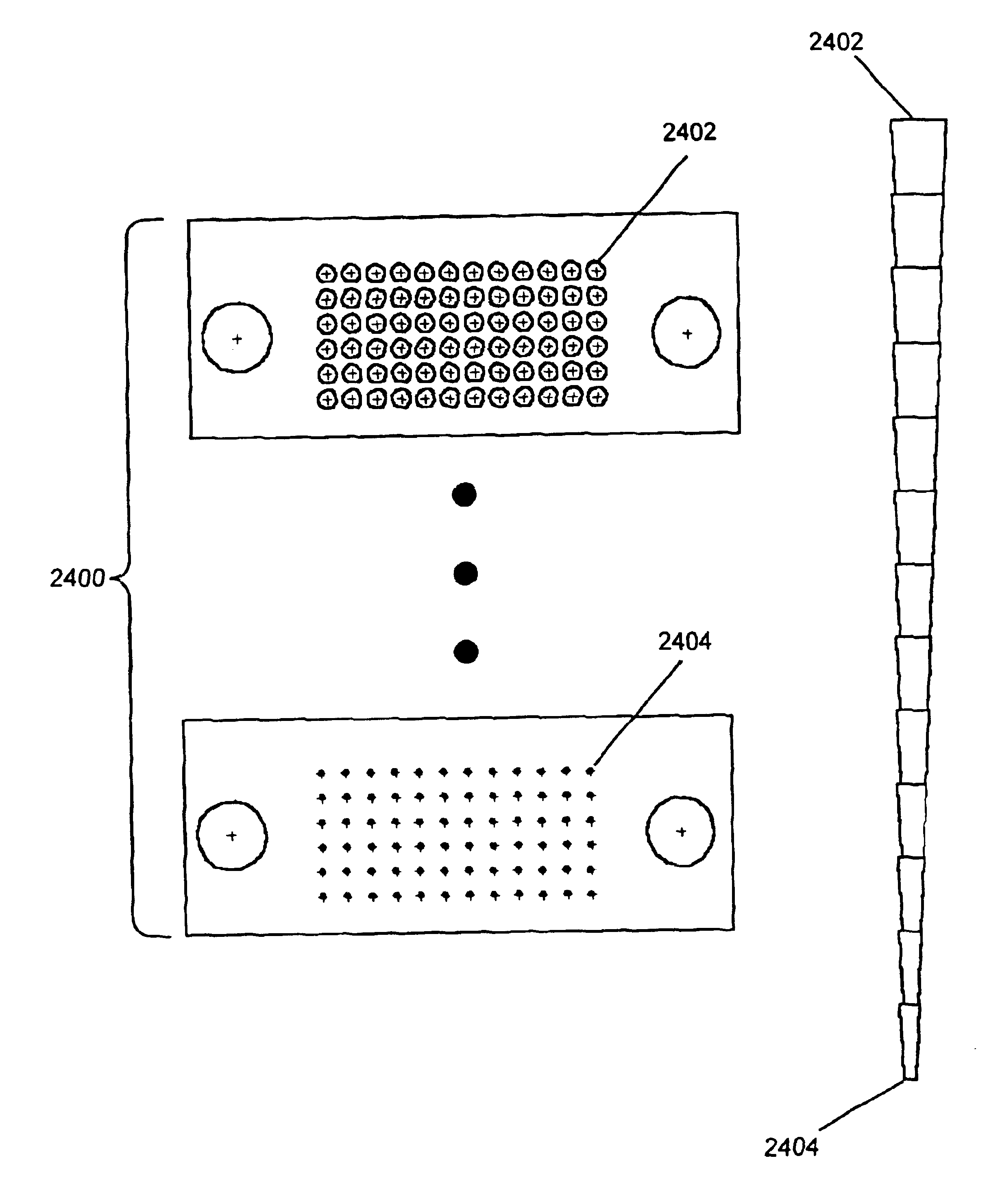
In addition, the process is not scalable to larger numbers of fibers (particularly 30 or more) because of inaccuracies and yield issues associated with molding technology and reliable production of ferrules for similar numbers of single mode fibers is even more difficult.
One manufacturer is known to have made a 5×12 connector array, but achieved such poor yields that they deemed an array of that size unmanufacturable.
Moreover, the cost of producing the pieces resulted in their being sold for $500 each, due to poor yield, and the mold for producing the pieces was destroyed during the process.
As such, the prior art has been forced to do without commercial connectors for such large arrays, because 5×12 arrays can not be reliably created and commercial connectors for larger format arrays (e.g. even a 6×12) are considered prohibitively difficult to even attempt.
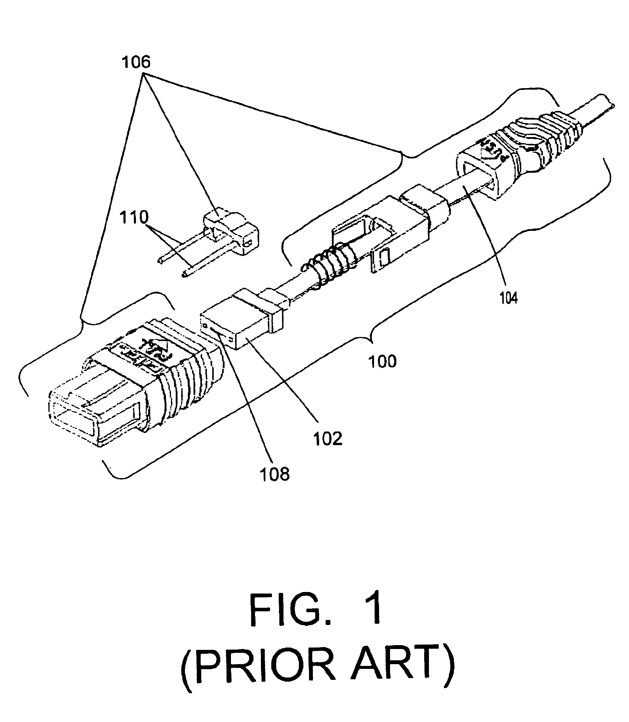
The ferrule area is very small, since ferrules for the above MTP, MPO, MPX or SMC connectors are about 0.07″ high, 0.3″ wide and 0.4″ deep, so molding or
machining of features in the ferrules of the sizes required to hold multiple optical fibers (which typically have about a 125 micron
diameter for a multimode fiber and a 9 micron
diameter core for a single mode fiber) is very difficult.
Since single mode fibers have an even smaller diameter than multimode fibers, molding or
machining ferrules to accommodate large arrays of single mode fibers is currently, for all practical purposes, impossible—particularly on a cost effective commercially viable scale.
Additionally, making ferrules for arrays is made more difficult due to process variations during production because, as the holes approach the edge of the ferrule, the
structural integrity of the walls decrease causing parts to have poor tolerance at the periphery, become overly fragile causing component collapse in some cases, or prohibiting removal of material from the inside of the piece that impedes or prevents fiber
insertion.
However, these attempts have not yielded a solution, particularly for the types of connectors mentioned above, because the inaccuracies of fiber production result in diameters of fibers which fluctuate within a 2 micron range (i.e. plus or minus 1 micron).
Even with multi-mode fibers (the best of which use 50 micron cores), a misalignment of 12 microns will cause unacceptable light loss for most applications.
For two-dimensional fiber arrays, the problem is even worse because the inaccuracy of the fiber is not limited to one direction.
Compounding the problem is the further fact that fiber inaccuracies stated as plus or minus 1 micron do not mean that fiber manufacturers guarantee that the fiber will be inaccurate by no more than 1 micron.
This means that most of the fiber should only be that inaccurate.
As a result, the larger the number of fibers, the more likely a problem due to fiber inaccuracy will occur because, for example, using the 16×16 array above, the array would have 256 times the chance (because there are 16×16=256 fibers) of having at least one of these statistically anomalous fibers in the group.
Others have attempted to align two dimensional arrays of fibers (e.g. 4×4 arrays) in a research setting, but none have applied their techniques to conventional connector technologies.
Moreover, the techniques are not suitable or readily adaptable for high yield, low cost,
mass production as demanded by the industry.
The approach used the
silicon pieces to hold the fibers but no attempt was made to integrate such an arrangement into a commercial connector.
While these
silicon pieces were able to hold fibers, they were not designed to be, and could not readily be, used with existing ferrule or connector technology.
Moreover, they could not be used for single mode fibers with any accuracy.
Thus, none of the above attempts have provided a viable solution to the problem of how to effectively create a
large format fiber array which: allows for high precision holding of large arrays of fibers, especially single mode fibers, is compatible with current commercially used connectors that attach two fiber bundles to each other or one
fiber bundle to a component containing an array of optical devices, such as lasers and / or detectors, and that allows for easy fiber termination in a rapid fashion at low production cost.
In addition, because of the above problems, there is presently no
large format ferrule apparatus that can maintain fibers at a low angle, or at a precisely specified angle, for good
optical coupling.
However, when dealing with
optical communication systems, faceplates can not be used because the light loss resulting from such a collimating arrangement is significant.
The faceplate technique (sometimes also referred to as
oversampling) is also incompatible with the use of single mode fibers or lasers (which are highly desirable for use in high speed, long distance
data transmission).
Hence, the collimating technique of using a faceplate, such as made for use in cameras, is an unworkable approach for opto-
electronic communication devices.
Unfortunately, the accuracy of stacking in the second dimension is limited by the accuracy of the thickness of the individual wafers, both on an absolute basis and on a relative basis, due to thickness variations over the area of the
wafer.
In addition, the stacked V-Groove technique requires such accuracy that individual stacks must be individually built up one at a time; a costly and inefficient process.
Presently, there are also no inexpensive two dimensional optical
waveguide combiners available for commercial applications or that can be used with a
fiber array.
This technique provides
robust control for a one-dimensional array, but cannot be extended into two dimensions since it is inherently a
planar process.

