Sintered cobalt-based alloys

Inactive Publication Date: 2005-10-25
FEDERAL MOGUL SINTERED PROD LTD
View PDF10 Cites 12 Cited by
  • Summary
  • Abstract
  • Description
  • Claims
  • Application Information

AI Technical Summary

Benefits of technology

[0028]Surprisingly, we have found that for the applications intended, i.e. sliding applications such as turbine shaft spindle bushings, actuator bushings, axial sliding bearings and hot-end sealing rings for example, the presence of tin within the sintered material does not present any significant disadvantages in performance, indeed, the presence of tin actually provides improved performance in parts subject to non-lubricated sliding. Furthermore, at t

Problems solved by technology

However, one drawback with the use of turbochargers has been the so-called “turbo lag” where the engine speed response to the throttle is delayed owing to the time needed for the exhaust gas turbine to increase speed and hence supply further air by the compressor for combustion.
Such designs are complex and hence very costly to manufacture.
Consequently, the alloys available for such applications tend to be relatively very expensive cobalt-b

Method used


Image

  • Sintered cobalt-based alloys

Examples


example 1

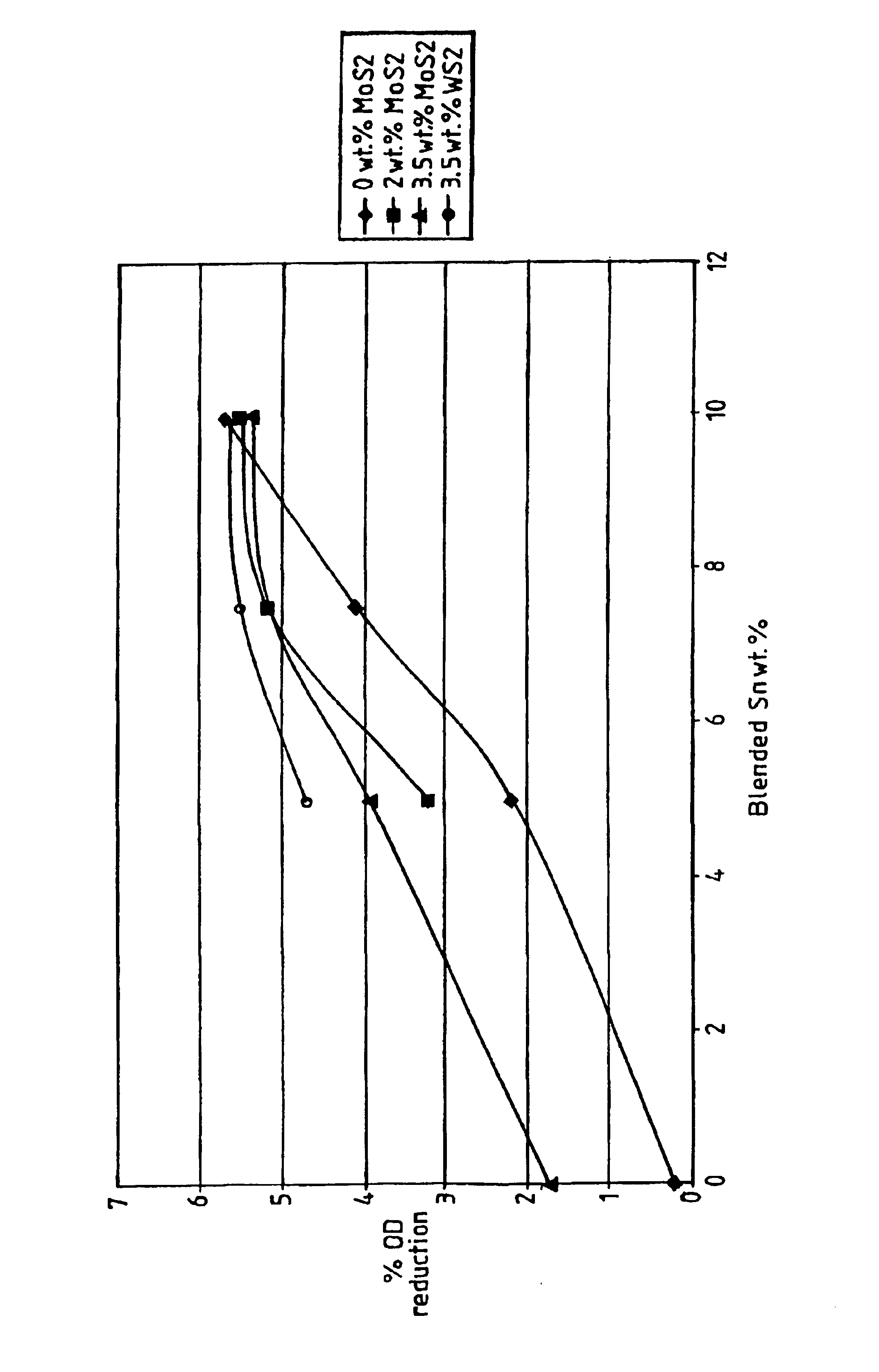
[0034]Atomised powder of Tribaloy T-400 (trade name) was mixed for 20 minutes in a Y-cone blender with 10 wt % of tin powder and 3.5 wt % of molybdenum disulphide powder. 1.5 wt % of a fugitive die lubricant, Kenolube (trade name), was also added. The blended powder was uniaxially cold pressed at 770 MPa and sintered in a walking beam furnace for approximately 15 minutes at 1170° C. with an atmosphere of 90% nitrogen:10% hydrogen. Visual and SEM-EDAX analysis revealed that original particle boundaries are not visible and particle shape cannot be determined. The microstructure consisted of Co—Mo—Cr particles approximately 12 microns in diameter in a matrix of Co—Mo—Cr—Sn, with a Co—Sn—Mo—Cr phase at particle boundaries having the appearance of solidified liquid. A Cr—S phase was present as a discrete 10 micron sized phase.

example 2

[0035]Atomised powder of Metco 45VF-NS (trade name) was mixed for 20 minutes in a Y-cone blender with 5 wt % of tin powder and 2 wt % of molybdenum disulphide powder. 1.5 wt % of Kenolube (trade name) die lubricant was also added. The blended powder was uniaxially cold pressed at 770 MPa and sintered in a walking beam furnace for approximately 15 minutes at 1170° C. with an atmosphere of 90% nitrogen:10% hydrogen. Visual and SEM-EDAX analysis revealed that original particle shape can be determined with particles having the composition Co—Cr—Ni—W—Sn. Inter-particle bonding had taken place the boundaries having 5 micron sized precipitates of Cr—Co—W—Ni—Mo and Cr—S—Sn—Co—Ni, with a Sn—Ni—Co—Cr phase having the appearance of solidified liquid. Within the particles there were 5 micron precipitates of Cr—Co—W—Ni—Mo.

example 3

[0036]Atomised powder Stellite 31 (trade name) was mixed for 20 minutes in Y-cone blender with 7.5 wt % of tin powder and 3.5 wt % of molybdenum disulphide powder. 1.5 wt % of Kenolube (trade name) die lubricant was also added. The blended powder was uniaxially cold pressed at 770 MPa and sintered in a walking beam furnace for approximately 15 minutes at 1170° C. with an atmosphere of 90% nitrogen:10% hydrogen. Visual and SEM-EDAX analysis revealed that original particle boundaries were visible due to the formation of precipitates. The particles were composed of Co—Cr—Ni—W—Fe—Sn and the precipitates were a mixture of Cr—S and Cr—W—Co—Mo, with a Sn—Ni—Co—Cr phase having the appearance of solidified liquid.


PUM

PropertyMeasurementUnit
Temperatureaaaaaaaaaa
Percent by massaaaaaaaaaa

Abstract

A sintered material and a method for the production thereof is described. The material comprises an alloy selected from one of the groups having a composition comprising in weight %: either Cr 5-30/Mo 0-15/Ni 0-25/W 0-15/C 0-5/Si 0-5/Fe 0-5/Mn 0-5/others 10 max/Co balance, or Cr 10-20/Mo 0-15/Co 0-20/W 0-5/Fe 0-20/Al 0-5/Ti 0-5/others 15 max/Ni balance; said alloy having incorporated therein from 3-15 weight % of Sn; and optionally from 1-6 weight % of a solid lubricant material.

Description

BACKGROUND OF THE INVENTION[0001]1. Technical Field[0002]The present invention relates to alloys based on cobalt and / or nickel and a method for the production thereof by a powder metallurgy route.[0003]2. Related Art[0004]Turbochargers for internal combustion engines have been in common use for many years in order to increase the power output and decrease the emissions of an engine. However, one drawback with the use of turbochargers has been the so-called “turbo lag” where the engine speed response to the throttle is delayed owing to the time needed for the exhaust gas turbine to increase speed and hence supply further air by the compressor for combustion. In recent years, however, turbocharger designs have been introduced which have largely overcome or at least greatly reduced the turbo lag problem.[0005]Reduction in turbo lag has generally been achieved in one of two main ways. Firstly, there are designs which have moving vanes in order to alter the approach gas speed and directi...

Claims


Application Information

Patent Timeline
IPC IPC(8): C22C32/00C22C1/04F01D25/16F01D5/28F16C33/04F16C33/12B22F3/10F16C33/10C22C19/05C22C19/07F16C33/14
CPCC22C1/0433C22C32/0089F01D5/28F01D25/166B22F1/0003B22F3/02B22F3/1007F16C33/121B22F2998/10F05C2201/0463F05C2201/0466F05D2240/50F05D2220/40F05D2300/132F16C2360/24B22F1/09
Inventor WHITAKER, IAIN ROBERTPAVEY, RICHARD JAMESON
Owner FEDERAL MOGUL SINTERED PROD LTD
Why Eureka
Try Eureka