Amorphous nano-scale carbon tube and production method therefor

Inactive Publication Date: 2005-11-01
OSAKA GAS CO LTD
View PDF5 Cites 21 Cited by
  • Summary
  • Abstract
  • Description
  • Claims
  • Application Information

AI Technical Summary

Benefits of technology

[0088](e) The amorphous nano-scale carbon tubes or a carbon material containing the carbon tubes are useful as a gas-storing material, a high elasticity material, a high strength material, a wear resistive

Problems solved by technology

This type of method is incapable of producing a product wherein the nano-scale molecules are controlled.
However, these techniques chiefly produce carbon nanotubes having a graphitic structure.
In the disclosed techniques, however, it is practically difficult to control straightness of molecules or shape factors such as diameter and length.
However, also in these techniques, it is practically difficult to control straightness of molecules, diameter, length and the like while maintaining the graphitic structure.
Therefore, it is extremely difficult to control the reaction parameters such as the amount of the starting material, resulting in production of CNTs having a graphitic structure and varying widely in shape.
Thus, the selective synthesis method or use of the amorphous carbon nanotubes have not been elucidated yet (Wenlow Wang et al: Electrochemical Society Proceedings Volume 97-14, 814(1997)).
As discussed above, it is practically difficult for th

Method used


Image

  • Amorphous nano-scale carbon tube and production method therefor
  • Amorphous nano-scale carbon tube and production method therefor
  • Amorphous nano-scale carbon tube and production method therefor

Examples


Example

EXAMPLE 1

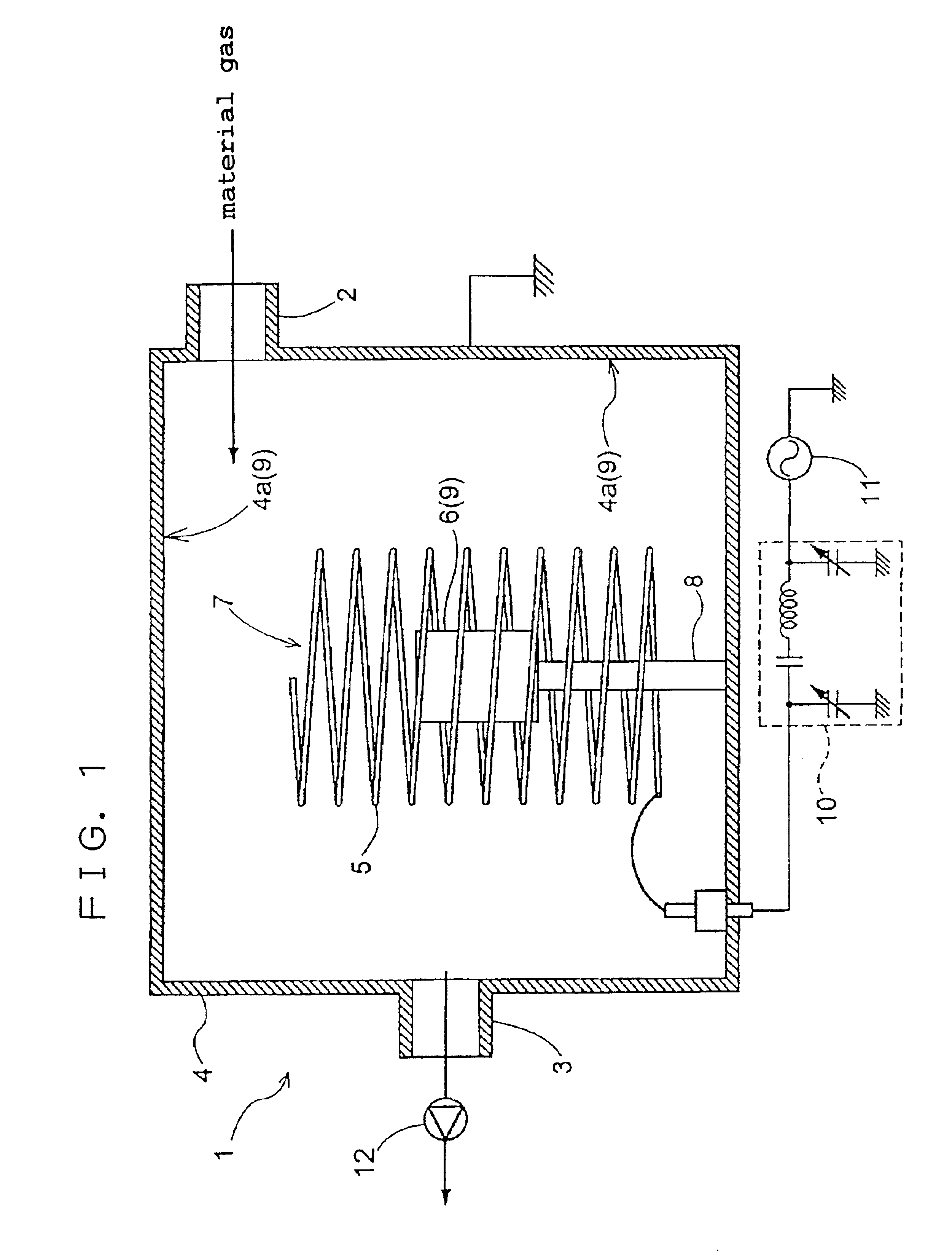
[0090]10 mg of an anhydrous iron chloride powder (having a particle size not greater than 500 μm) was dusted uniformly over a PTEE film (60 μm×10 mm×10 mm), and the film was then excited by plasma. FIG. 1 shows the outline of a thin film forming apparatus 1 used. It is a matter of course that an apparatus having a structure other than that shown in FIG. 1 can be used in the present invention.

[0091]The thin film forming apparatus 1 shown in FIG. 1 comprises a reactor 4 equipped with a material gas inlet 2 and a gas discharge port 3, a first electrode 5 made of a helical wire and provided in the reactor 4 in an insulated manner, and further comprises a support member 8 electrically contacted with an object 6 and supporting the object 6 within a plasma generation area 7 surrounded by the first electrode 5; the support member 8, in combination with an internal wall 4a of the reactor 4, being electrically grounded to serve as a second electrode 2. Consequently, application of a ...

Example

EXAMPLE 2

[0099]10 mg of an anhydrous iron chloride powder (having a particle size not greater than 500 μm) was dusted uniformly over a PTFE film (60 μm×10 mm×10 mm), and the film was placed in a vacuum furnace. The pressure in the furnace was reduced to 0.1 Pa, and then the film was irradiated with a laser beam.

[0100]The conditions for laser beam irradiation were as follows.

[0101]AtmosphereHeInternal pressure500 torrTemperature800° C.Input laser beam wavelength248 nmInput laser beam power density17 mJ / pulse / cm2Number of cycles of input1 Hzlaser beamPeriod of irradiation with30 minutesthe input laser beam

[0102]After completion of the reaction, formation of amorphous nano-scale carbon tubes was confirmed by SEM and X-ray diffraction. The product obtained in this Example had a diameter and length approximately equal to that of Example 2.

Example

EXAMPLE 3

[0103]10 mg of an anhydrous iron chloride powder (having a particle size not greater than 500 μm) was dusted uniformly over a PTFE film (60 μm×10 mm×10 mm). The film was placed in a vacuum furnace. The furnace was purged with nitrogen 3 times, and the pressure in the furnace was reduced to 3 Pa. Then, the film was vacuum baked at 900° C. for 10 minutes.

[0104]Formation of amorphous nano-scale carbon tubes was observed by SEM and X-ray diffraction. The product obtained in this Example had a diameter and length approximately equal to that of Example 1.

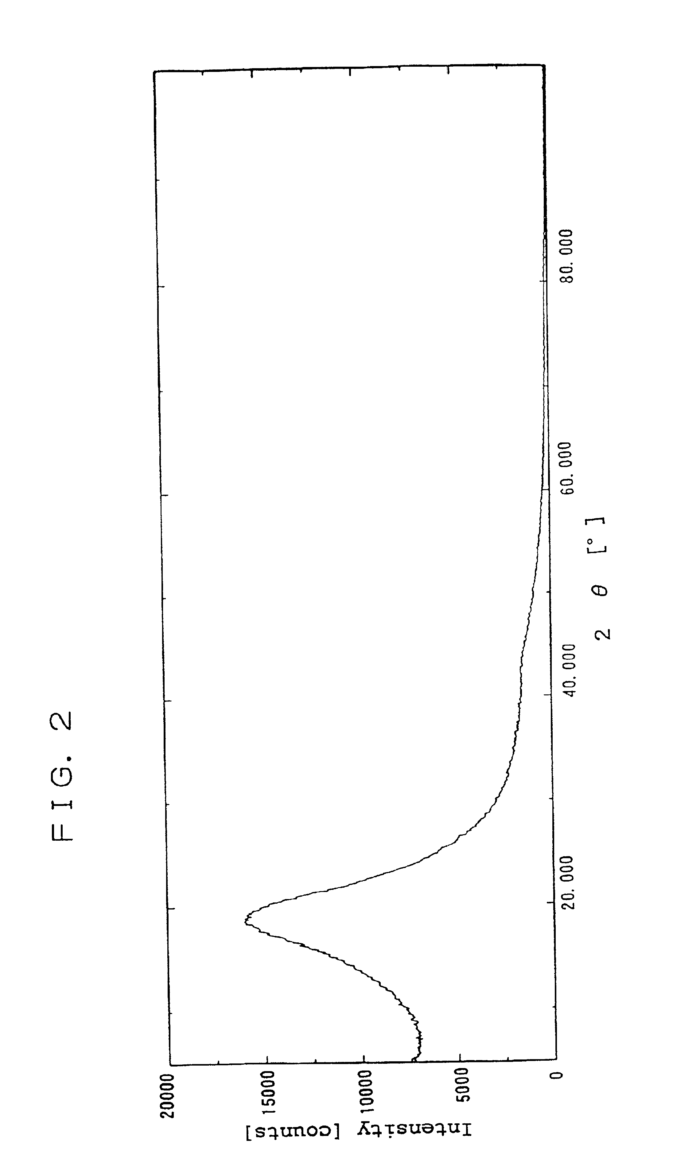
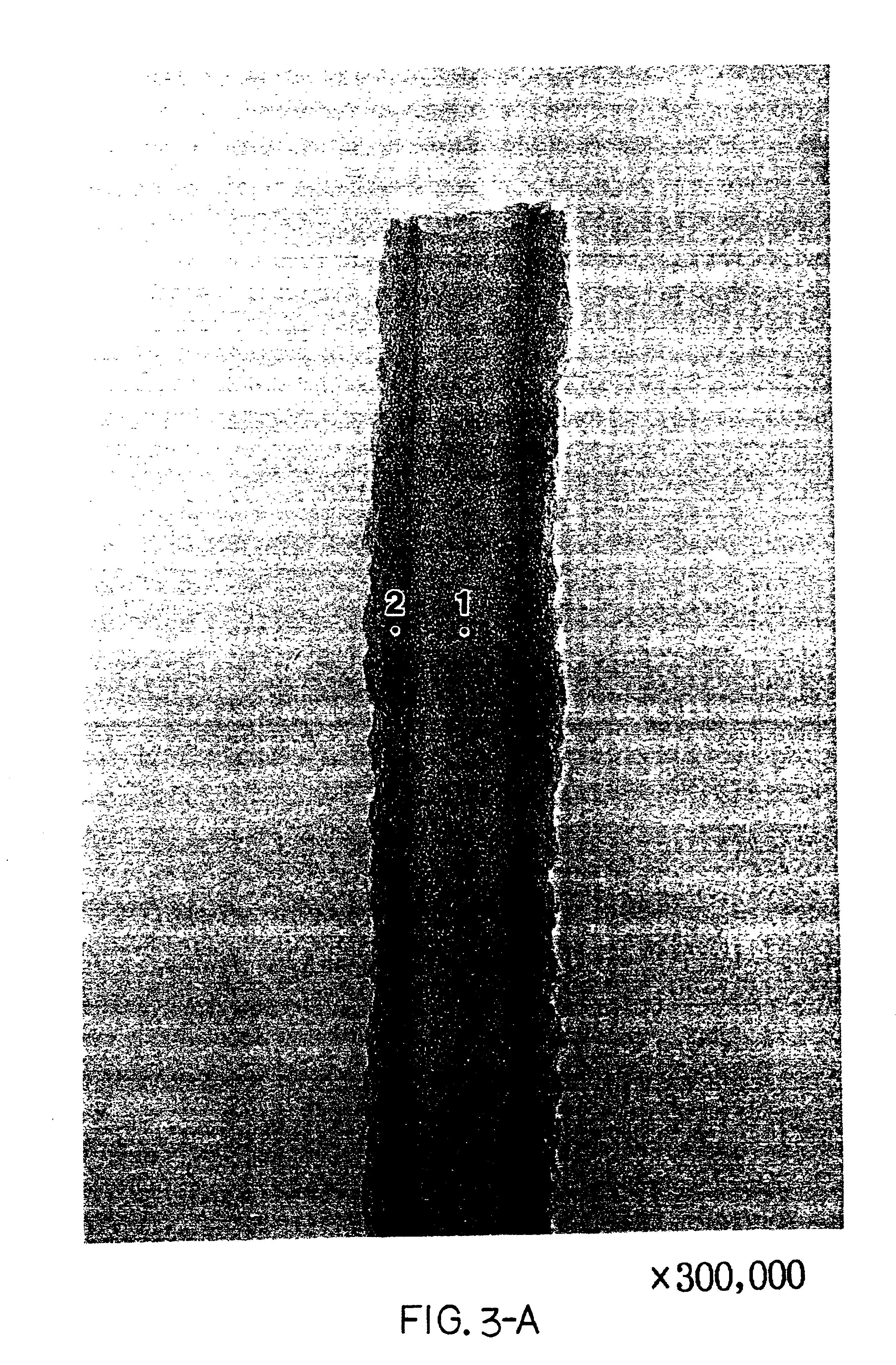
[0105]FIG. 3-A and FIG. 3-B are TEM photographs of an amorphous nano-scale carbon tube obtained. FIG. 4 is an X-ray diffraction chart of the carbon tubes thus obtained.

[0106]TEM observation revealed that, in each of the obtained amorphous nano-scale carbon tubes, the dimension in the planar direction of the hexagonal carbon layers is smaller than the diameter of the carbon tube. The X-ray diffraction angle (2θ) was 18.9 degrees; ...


PUM


Abstract

Straight, nano-scale-order amorphous carbon tubes having a long-term stable ability for storing various kinds of gases and being stable in shape, and a novel process for producing said carbon tubes with high purity, high yield and high mass-productivity are provided.
The amorphous nano-scale carbon tubes are prepared by subjecting a heat-decomposable resin having a decomposition temperature of 200 to 900° C. to an excitation treatment in the presence of a metal powder and/or a metal salt, or by subjecting a carbon material containing —C≡C— and/or ═C═ to a heat-treatment at 3000° C. or lower.

Description

TECHNICAL FIELD[0001]The present invention relates to amorphous nano-scale carbon tubes each of which comprises carbon as a main framework and has a diameter of 0.1 to 1000 nm and a hollow fiber shape; a carbon material containing the amorphous nano-scale carbon tubes; and a method for producing the amorphous nano-scale carbon tubes or the carbon material.BACKGROUND ART[0002]Conventionally, carbon fibers are produced by forming a starting material such as pitch or polyacrylonitrile into fibers while maintaining the main chain framework of the starting material. This type of method is incapable of producing a product wherein the nano-scale molecules are controlled.[0003]Carbon nanotubes (hereinafter referred to as “CNTs”), which have been attracting attention recently, can be roughly regarded as fibers controlled at the molecular level. CNTs are produced by the carbon arc method, sputtering, laser beam irradiation or like technique, using graphite or like starting carbon material in ...

Claims


Application Information

Patent Timeline
IPC IPC(8): C01B3/00C01B31/00C01B31/02F17C11/00
CPCB82Y30/00B82Y40/00C01B3/0021C01B3/0078C01B31/0233F17C11/00F17C11/005C01B2202/36Y02E60/321Y02E60/325Y02E60/327C01B32/162Y02E60/32C01B32/05B82B1/00
Inventor MATSUI, HISAJINISHIDA, RYOICHINISHINO, HITOSHIYAMAGUCHI, CHIHARUNAKAOKA, HARUYUKITAKEZAKI, KAZUHIROSASAKI, KATSUHIRO
Owner OSAKA GAS CO LTD
Why Eureka
Try Eureka