Fuel cell power generation method and system

a technology of fuel cell and power generation method, which is applied in the direction of biological sludge treatment, liquid degasification, separation process, etc., can solve the problems of limiting the level of methane enrichment, large size of the absorption apparatus, and small dioxide absorption capacity of the treatment water, etc., to achieve low running cost, high running cost, and simplified process

Inactive Publication Date: 2005-11-29
EBARA CORP
View PDF7 Cites 18 Cited by
  • Summary
  • Abstract
  • Description
  • Claims
  • Application Information

AI Technical Summary

Benefits of technology

[0026]Conventionally, in desulfurizing the digestion gas, it is a common practice to use a combination of a primary dry adsorption desulfurization after the fermentation step and a deep dry adsorption desulfurization before the hydrogen production step. Therefore, this conventional method is disadvantageous in that, particularly when the hydrogen sulfide load is high, the adsorbent has to be frequently replaced and this is troublesome and incurs high running cost. By contrast, according to the present invention, it is possible to perform, in a single step (i.e., the alkaline absorption step), the desulfurization of the digestion gas, the separation of carbon dioxide from the digestion gas, i.e., methane enrichment, and the stabilization of the concentration of methane in the pretreated gas. This can realize a simplified process with a low running cost.
[0027]When the method in which hydrogen sulfide is absorbed and removed in the alkaline absorption step is employed, the absorbed hydrogen sulfide is accumulated in the absorbent solution in an early stage of the operation. However, after the concentration of hydrogen sulfide in the absorbent solution reaches a certain value, the hydrogen sulfide, together with carbon dioxide, is stripped in the alkaline absorbent solution regeneration step and is transferred to the regeneration off-gas. According to the present invention, particularly when the concentration of hydrogen sulfide in the digestion gas is high, i.e., when the load of hydrogen sulfide is high, a biodesulfurization step characterized by low running cost can be provided as the desulfurization means to biodecompose hydrogen sulfide contained in the regeneration off-gas.
[0028]According to the biodecomposition of hydrogen sulfide, hydrogen sulfide is oxidized by microorganisms into sulfur or sulfuric acid, and hence the supply of oxygen is necessary. Conventionally, the biodesulfurization could not be adopted as the method for the desulfurization of digestion gas, because the introduction of air or oxygen into the digestion gas adversely affects the subsequent hydrogen production step. By contrast, according to the present invention, as described above, hydrogen sulfide contained in the digestion gas is once transferred from the digestion gas to the regeneration off-gas, and hence the adoption of the biodesulfurization becomes possible. In addition, according to the present invention, since an oxygen-containing combustion exhaust gas discharged from the hydrogen production step or an oxygen-containing cathode vent gas discharged from the fuel cell power generation step is used as the regeneration gas for the alkaline absorbent solution,

Problems solved by technology

However, the carbon dioxide absorption capacity of the treatment water is so small that the size of the absorption apparatus has to be very large.
Further, the dissolved oxygen and dissolved nitrogen in the treatment water are transferred to the gas after the treatment, and therefore oxygen and nitrogen contained in the gas after the absorption amount to several percents, thus limit the level of the enrichment of methane, and adversely affect the subsequent hydrogen production step and the fuel cell power generation step.
On the other hand, in the PSA or the membrane separation, power for increasing or decreasing the pressure of gas is necessary, and, in addition, the recovery rate of methane is low, disadvantageously leading to a lowered energy efficiency of the system.
As for the dry adsorption of hydrogen sul

Method used


Image

  • Fuel cell power generation method and system
  • Fuel cell power generation method and system
  • Fuel cell power generation method and system

Examples


first embodiment

[0040]A fuel cell power generation system according to the present invention will be described in detail with reference to the accompanying drawings.

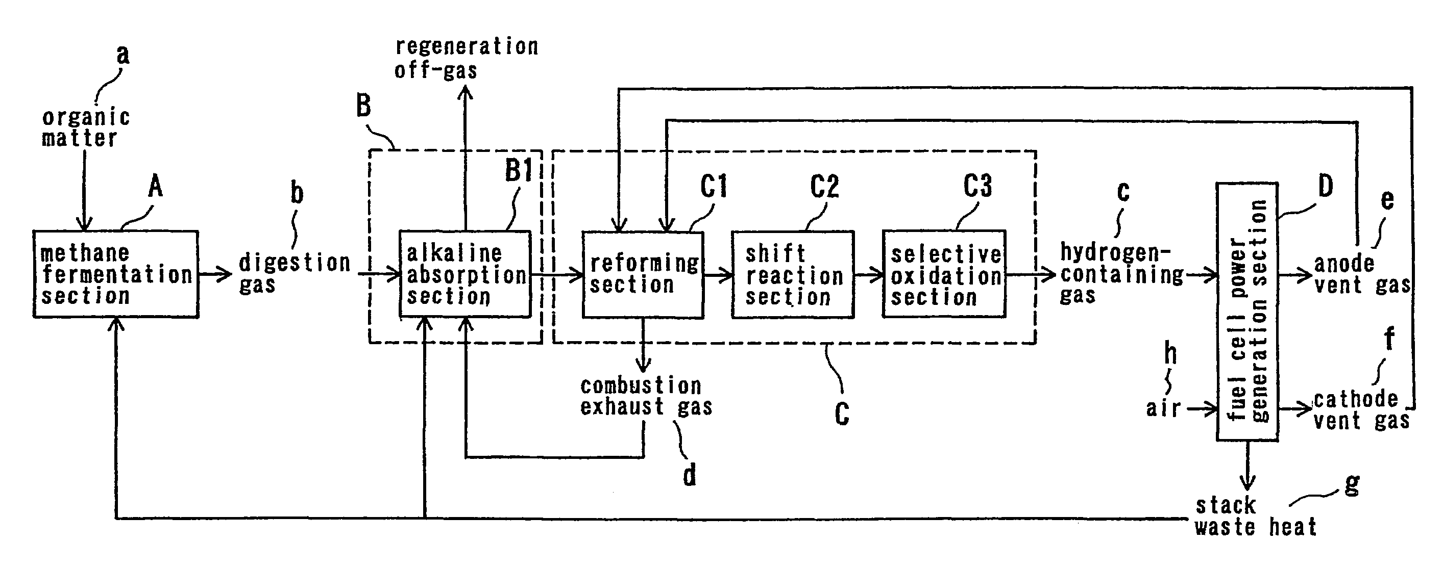
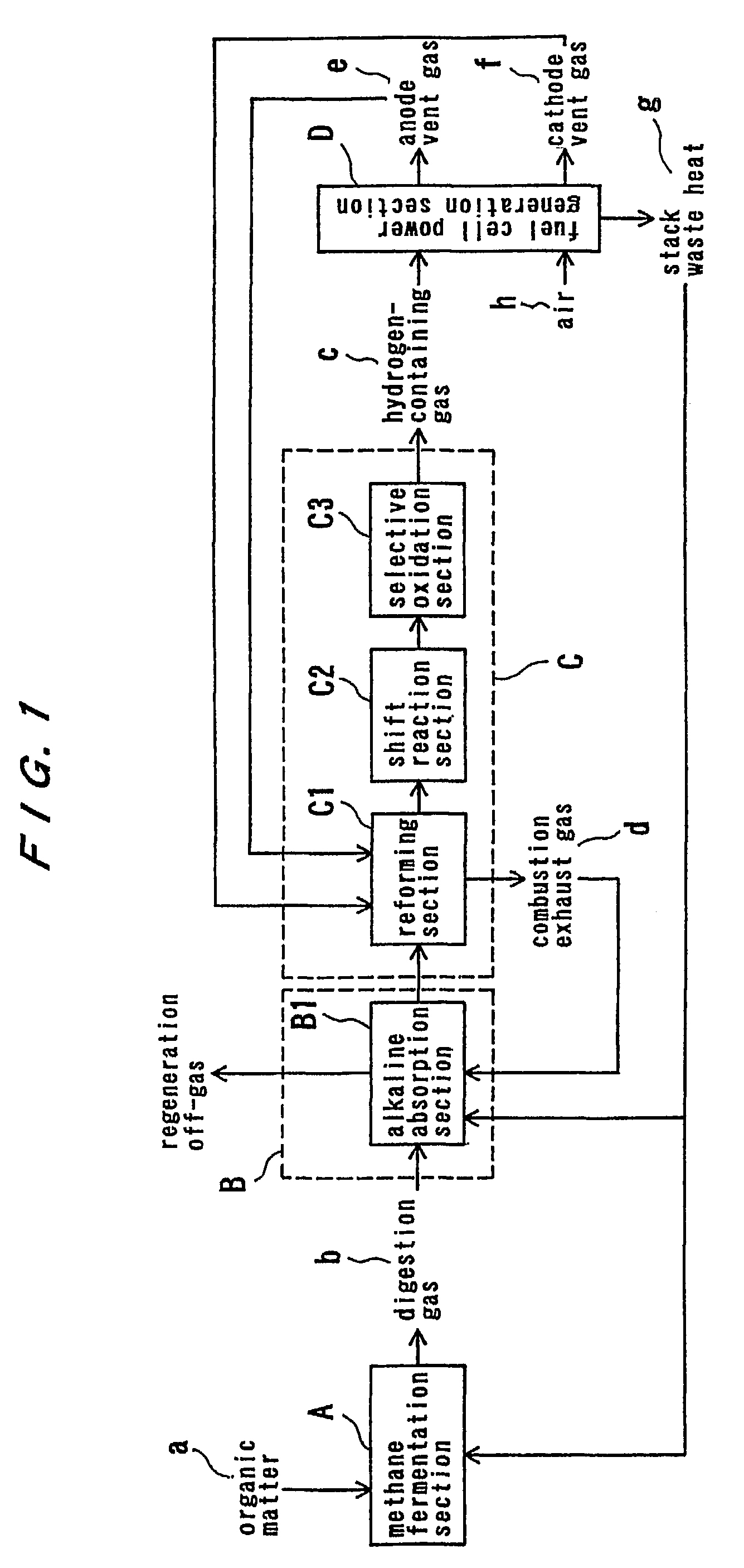
[0041]FIG. 1 is a schematic block diagram showing the fuel cell power generation system according to the first embodiment.

[0042]As shown in FIG. 1, in this embodiment, organic matter a is fermented in a methane fermentation step A. An anaerobic digestion gas b produced in the methane fermentation step A is pretreated in a pretreatment step B, and the pretreated gas is processed in a hydrogen production step C to produce a hydrogen-containing gas c which is then supplied to a fuel cell power generation step D to generate electricity.

[0043]The hydrogen production step C comprises a reforming step C1 for catalytically reforming methane, contained in the gas pretreated in the pretreatment step B, with steam into hydrogen and carbon monoxide; a shift reaction step C2 for catalytically converting carbon monoxide, contained in the gas after th...

second embodiment

[0076]Next, the fuel cell power generation system according to the present invention will be described in detail with reference to the accompanying drawings.

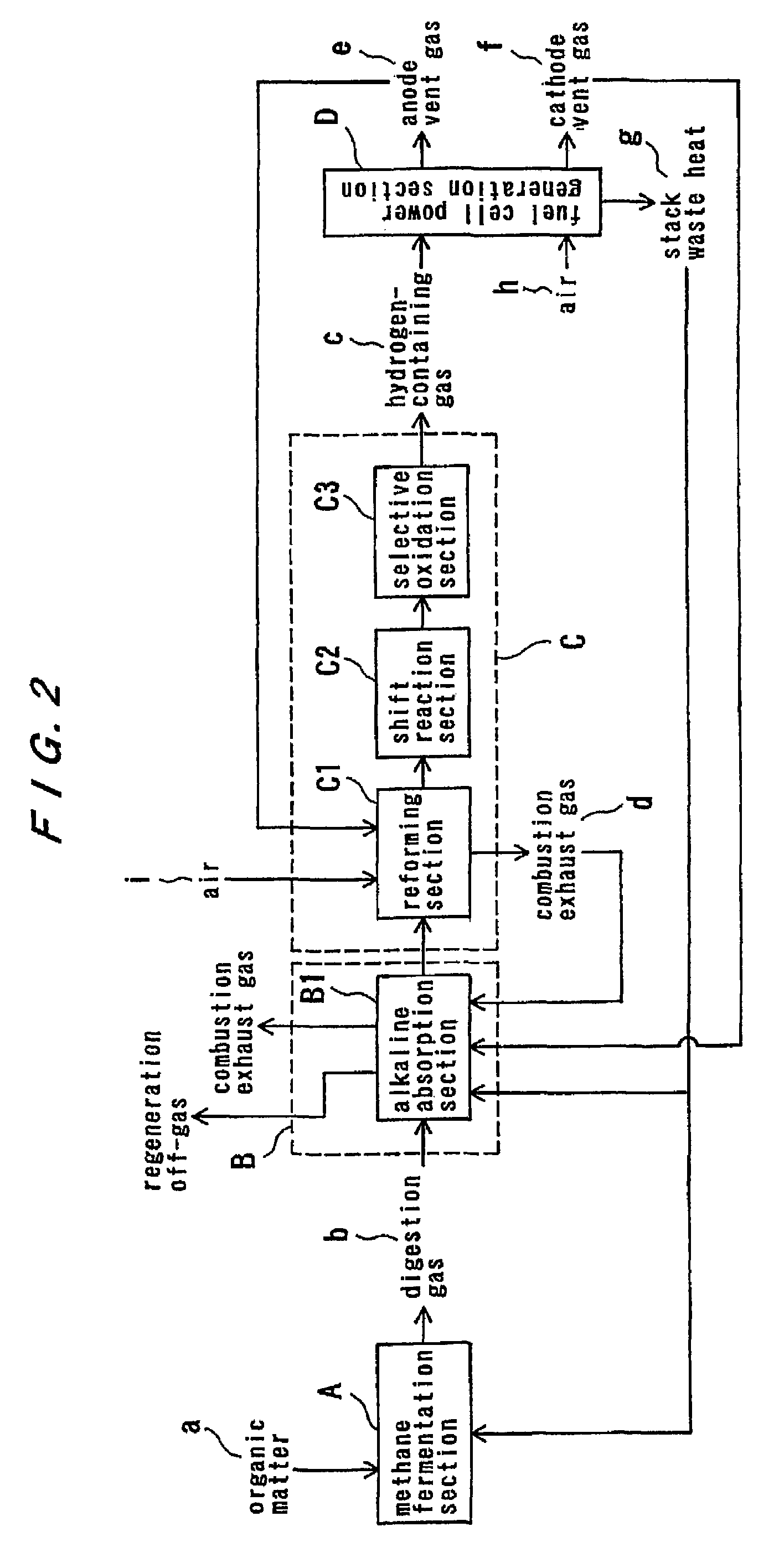
[0077]FIG. 2 is a schematic block diagram showing the fuel cell power generation system according to this embodiment. In FIG. 2, steps and elements identical to or corresponding to those in FIG. 1 have the same reference characters as used in FIG. 1. In the second embodiment, portions not specifically referred to herein are the same as those in the first embodiment.

[0078]According to this embodiment, as shown in FIG. 2, the combustion exhaust gas d discharged from the reforming step C1 in the hydrogen production step C is utilized as a heat source for regeneration in the alkaline absorption step B1, while the cathode vent gas f discharged from the fuel cell power generation step D is utilized as a regeneration gas in the alkaline absorption step B1. Further, a part of the stack waste heat g from the fuel cell power generation st...

third embodiment

[0085]Next, the fuel cell power generation system according to the present invention will be described in detail with reference to the accompanying drawings.

[0086]FIG. 3 is a schematic block diagram showing the fuel cell power generation system according to this embodiment. In FIG. 3, steps and elements identical to or corresponding to those in FIG. 1 have the same reference characters as used in FIG. 1. In the third embodiment, portions not specifically referred to herein are the same as those in the first embodiment.

[0087]According to this embodiment, as shown in FIG. 3, the combustion exhaust gas d discharged from the reforming step C1 within the hydrogen production step C is utilized as a regeneration gas in the alkaline absorption step B1. In this system, of course, the combustion exhaust gas d discharged from the reforming step C1 may be utilized as a heat source for the regeneration in the alkaline absorption step B1, while the cathode vent gas f discharged from the fuel cell...


PUM

PropertyMeasurementUnit
Temperatureaaaaaaaaaa

Abstract

A hydrogen-containing gas suitable for use in a fuel cell, especially in a proton exchange membrane fuel cell, is produced from a digestion gas (b) yielded in methane fermentation of organic matter (a), and is then supplied to the fuel cell to generate electricity. A fuel cell power generation method comprises a methane fermentation step (A) for subjecting organic matter to methane fermentation, a pretreatment step (B) for pretreating digestion gas yielded in the methane fermentation step, a hydrogen production step (C) for producing hydrogen-containing gas (c) from the gas which has been pretreated in the pretreatment step, and a fuel cell power generation step (D) for supplying the hydrogen-containing gas produced in the hydrogen production step to a fuel cell to generate electricity. The pretreatment step comprises an alkaline absorption step (B1) for absorbing carbon dioxide or carbon dioxide and hydrogen sulfide contained in the digestion gas yielded in the methane fermentation step into an alkaline absorbent solution.

Description

TECHNICAL FIELD[0001]The present invention relates to a technology for recovering chemical energy of organic matter in the form of a hydrogen gas and a technology for converting hydrogen gas to electric energy with high efficiency, and more particularly to a system for producing a hydrogen gas or a hydrogen-containing gas by methane fermentation of organic wastes such as relatively highly concentrated organic waste water or organic slurry to produce a digestion gas, and then processing of the thus produced digestion gas, and an electric generating system for generating electricity by supplying the produced hydrogen gas or hydrogen-containing gas to a fuel cell. The organic wastes include waste water discharged from food production, wastes from livestock farms, and excess sludge produced in sewage treatment plants or the like.[0002]The present invention is also applicable to a methane fermentation gas produced in landfills or the like.BACKGROUND ART[0003]In recent years, there has be...

Claims


Application Information

Patent Timeline
IPC IPC(8): B01D19/00B01D53/14B01D53/52C01B3/38C01B3/48C02F3/28C02F11/04H01M8/04H01M8/06H01M8/10
CPCC01B3/38C01B3/48H01M8/0662C01B2203/0233C01B2203/0283C01B2203/044C01B2203/047C01B2203/066C01B2203/1241C01B2203/1258H01M8/0612H01M8/0618H01M8/086H01M8/1002Y02C10/06Y02E50/343Y02E60/50Y02P20/129H01M8/1007Y02C20/40Y02E50/30
Inventor SU, QINGQUANKINOSHITA, KAZUOTANAKA, YASUOTOGO, TOMOHIRO
Owner EBARA CORP
Why Eureka
Try Eureka