Electromagnetic-acoustic imaging

a technology of electromagnetic and acoustic imaging and imaging apparatus, which is applied in the field of medical diagnostic equipment, can solve the problems of high facility cost, lack of portability, and high cost of imaging apparatus which relies on conventional mri, and achieves excellent contrast, large intrinsic contrast, and better resolution

Inactive Publication Date: 2005-12-13
EMERSON JANE F +3
View PDF11 Cites 68 Cited by
  • Summary
  • Abstract
  • Description
  • Claims
  • Application Information

AI Technical Summary

Benefits of technology

[0014]For medical applications, EMAI offers diagnostic utility because electrical conductivity differences are large between tissue types and disease states. For example, it has been shown that conductivity values for malignant (cancerous) lesions may be 50 fold higher than those for benign lesions. As a result, the ultrasound generated at a target site by the electrical stresses at the interfaces provides an effective means of imaging the boundaries between different types of normal tissues and the boundaries between normal and cancerous tissues. When used as an adjunct to conventional ultrasound imaging of tissue acoustic parameters, the proposed ultrasound imaging of tissue conductivity properties is especially convenient, because of the ease of co-registration of the two types of images. Medical applications for this technique include, but are not limited to: characterizing lesions in the breast, thyroid, prostate or other pelvic regions as benign or malignant; volume measurements of fluid spaces such as cysts, abdominal cavity, heart, and blood vessels; and flow measurement in blood vessels.
[0020]Imaging from ultrasound generated by electromagnetically induced RF ohmic currents offers considerable advantages, in cost, size, and the provision of complementary information, while avoiding the limitations inherent in other approaches.
[0022]When compared to Ultrasound, the present invention can obtain excellent contrast because it measures the large intrinsic electrical conductivity differences between tissue types and between abnormal and normal tissue (e.g., 4000%, see Table I). The 40-fold difference in intrinsic tissue electrical conductivity should constitute a considerable advantage for contrast. The present invention does not require the use of intense ultrasound waves. Better resolution is expected since the ultrasound does not need to travel two ways (from a transducer to the tissue and back to the detector), but only from the tissue to the detector. At the same time, complementary information is provided (electrical vs. direct mechanical properties), so that consideration is given to using both compact and low cost approaches to more fully characterize the organs of interest. When this is done, it is especially straightforward to co-register the images of electrical conductivity variations with the conventional images of tissue acoustic properties.
[0023]When compared with non-resonant RF, the present invention capitalizes on the large intrinsic contrast of tissues due to the 4000% variation in electrical properties among different tissues, but avoids the resolution limitations imposed by the long wavelengths of the RF electromagnetic waves. Good resolution can be achieved by using the shorter wavelength ultrasound waves for imaging the conductivity changes.
[0024]When compared with RF current tomography, the present invention capitalizes on the large intrinsic contrast of tissues due to the 4000% variation in electrical properties among different tissues, but avoids the poor resolution imposed by the fact that the currents satisfy Laplace's equation rather than a wave equation. The present invention does not require any direct electrical electrode contact with the patient (although direct electrode contact is an option). Good resolution is achieved by imaging with the short wavelength ultrasound waves generated by the electric fields (five orders of magnitude shorter than the illuminating RF). The most direct way of obtaining good images is with acoustic lensing (although tomographic methods can also be used with the shorter wavelength ultrasound waves).

Problems solved by technology

An imaging apparatus which relies on conventional MRI is expensive, bulky, lacks portability, and is associated with high facility costs because of the shielding and cryogenic requirements for strong magnetic fields.
However these large variations deflect the paths of the microwaves traversing the body and thus distort the image produced.
This process is unstable in the sense that a small change (e.g. due to noise or interference) in the received observational data produces large changes in the computed image.
A problem with magnetic detection at sub-microwave frequencies is its inherently low resolution.
Consequently, the size and cost of the equipment may only be a fraction of that for an MRI scanner.

Method used


Image

  • Electromagnetic-acoustic imaging
  • Electromagnetic-acoustic imaging
  • Electromagnetic-acoustic imaging

Examples


experiment 1

B1. Experiment 1

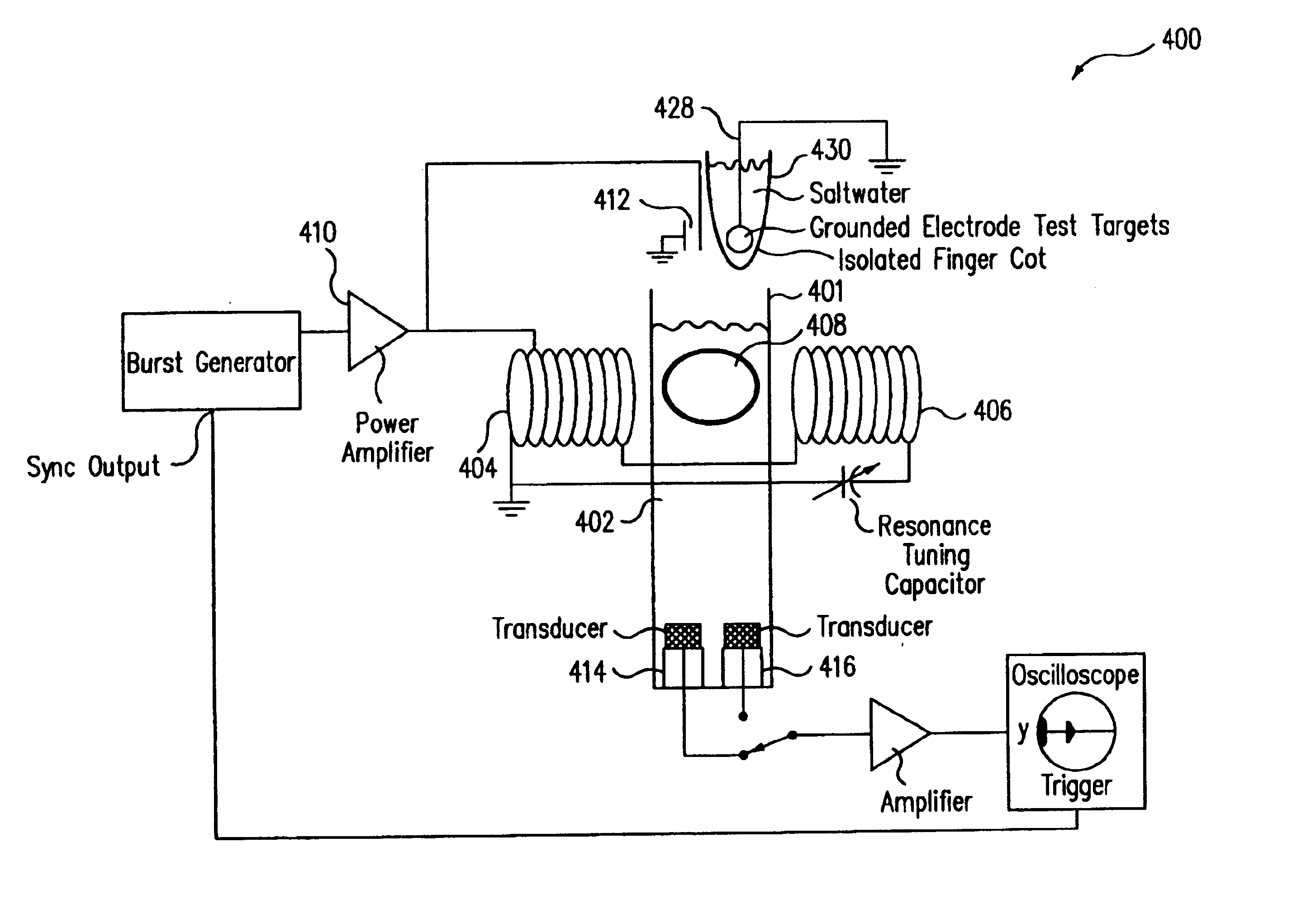
[0160]FIG. 4A is a schematic drawing of an experimental apparatus 400, used to demonstrate that ultrasound can be generated by surface charges at an interface between conducting and non-conducting media. FIG. 4A shows a vertical cylinder 401 holding a liquid 402, such as saltwater and a pair of horizontal solenoids 404 and 406 yoked together, providing a magnetic induction field in immersion volume 408. An RF power amplifier 410 feeds solenoids 404 and 406. A capacitor probe 412, which can be inserted in cylinder 401, includes two conducting plates separated by a thin gap. Two piezoelectric sensors 414 and 416 are located at the bottom of cylinder 401. A pulsed RF current source is used to excite the conducting plates of the capacitor probe 412 and / or solenoids 404 and 406.

[0161]In Experiment 1, the excitation frequency is 2.25 MHz, and the duration of the pulse is 10 microseconds. The resonant response of piezoelectric (PZT) sensors 414 and 416 is at 2.25 MHz, and 5...

experiment 2

B2. Experiment 2

[0165]In Experiment 1, ultrasound generation was demonstrated from surface charges induced on an interface between a conducting region and a non-conducting region. Experiment 2 demonstrates ultrasound generation at an interface between two regions of different conductivity. In Experiment 2, ultrasound generation is demonstrated from surface charges induced on an interface between two regions of different conductivity.

[0166]The apparatus 460 of Experiment 2 is shown in FIG. 4B, which includes two intersecting PVC ½ inch pipes, one horizontal 462 and the other vertical 464. A 5 MHz PZT detector 466 was placed at the bottom of vertical pipe 464, about 6 inches below horizontal pipe 462. Two electrodes 468 and 470 were placed in the horizontal pipe to provide horizontal current. A ring electrode 472 was placed in vertical pipe 464 as well, below the intersection with horizontal pipe 462. In Experiment 2, ring electrode 472 was disconnected when the pair of electrodes 468...


PUM


Abstract

Ultrasound induced by RF irradiation within FDA exposure limits is produced with sufficient signal-to-noise ratio to allow acquisition of sub-millimeter resolution images within practical time frames.

Description

BACKGROUND[0001]1. Field of the Invention[0002]The present invention relates to medical diagnostic equipment, and more particularly to medical diagnostic equipment using radio-frequency (RF) fields, ultrasonic detectors and signal processors, to produce visual images and digital outputs.[0003]2. Description of Related Art[0004]Radio frequency (RF) electromagnetic (EM) fields are widely used for medical diagnostics in magnetic resonance imaging (MRI). In MRI, RF is used to excite coherent precession of nuclear magnetic moments in a strong static background magnetic field. Precessing moments provide imaging information through the subsequent RF fields that they generate. These subsequent fields depend on the local densities of moments, their relaxation times, and precession frequencies, which in turn depend upon the local chemical and physical environment of the precessing nuclei. Detection of the subsequent fields has provided images of molecular properties with good spatial resoluti...

Claims


Application Information

Patent Timeline
Patent Type & Authority Patents(United States)
IPC IPC(8): A61B5/00A61B8/13
CPCA61B5/0073A61B5/0095A61B5/416A61B8/13
Inventor CERWIN, STEPHEN ANTHONYCHANG, DAVID B.DRUMMOND, JAMES E.EMERSON, JANE F.MCNAUGHTON, STUART
Owner EMERSON JANE F
Why Eureka
Try Eureka