Electrochemical device using multicomponent composite membrane film

a composite membrane film and electronic device technology, applied in the field of electronic elements, can solve the problems of lithium ion polymer batteries lithium ion compounds that are difficult to manufacture, and batteries that are flammable and explosive, and achieve good ionic conductivity and mechanical properties, good adhesion, and easy manufacturing

Inactive Publication Date: 2006-03-21
TORAY BATTERY SEPARATOR FILM +1
View PDF11 Cites 103 Cited by
  • Summary
  • Abstract
  • Description
  • Claims
  • Application Information

AI Technical Summary

Benefits of technology

[0021]It is an object of the present invention to provide an electrochemical element comprising electrochemical cells which are multiply-stacked, wherein a separator film or a separator layer is made from a novel multi-component composite film consisting of a porous gellable polymer layer and a support layer film, so that the battery is easy to manufacture and has a structure making efficient use of the space available while considering the prior art, and wherein the film has good adhesion between an electrode and a polymer electrolyte, and good ionic conductivity and mechanical properties.

Problems solved by technology

These lithium ion batteries, however, have safety problems resulting from the use of organic electrolyte, which causes the batteries to be flammable and explosive.
In addition, lithium ion compounds are difficult to manufacture.
These lithium ion polymer batteries, however, have relatively low capacity compared to lithium ion batteries, and in particular, they have insufficient discharging capacity at low temperatures, and thus they need to be improved.
This structure, however, has a small radius of curvature at the center portion of the spiral, which often results in extreme stresses at the bending surface of the electrode, often causing exfoliation of the electrode.
This facilitates the deposition of lithium metal at the center portion of the electrode during the repeated charge and discharge of the battery, which may shorten the lifespan of the battery while degrading its safety.
This method is not free from the aforesaid problems of reduced lifespan and safety, but rather it has increased the problems caused by the decrease in the radius of curvature due to the oval shape.
Also, the problem of reduced performance is greater because manufacturing a tight spiral structure is inherently impossible.
Furthermore, a discrepancy between the oval shape of the jellyroll and the rectangular shape of the container reduces the rate of utilized volume.
These proposals, however, only provide partial solutions to the problems or they cause other problems that are more difficult to solve, so they have not become practical.
The inventors of the present invention have tried to replicate this process but they found that it was difficult to manufacture the cells in such a way.
The laminated cells were so stiff that they were difficult to fold, and when they were folded by exerting force, a problem arose in the folded area because it was fractured in a manner similar to that of the jellyroll cells.
Thus, the problems of exfoliation, cracks, and crumbling, encountered in jellyroll structures, also occur frequently.
Also, the cells with this structure are inherently prone to snapping, and therefore the possibility of making a practically applicable battery is very low.
It provides a fundamental way of avoiding exfoliation of the electrodes by leaving out the electrodes at the folding portions and providing connections only through the use of current collectors and separator layers or polymer electrolyte portions, but it is difficult to compose such a cell.
Furthermore, too high a volume of the current collectors is used so electrolyte volume is reduced.
Thus, the structure is not very practical because it has many inefficient factors.
But the liquid electrolyte may leak out of the polymer separator due to its high fluidity.
In addition, the liquid electrolyte cannot provide adhesion between an electrode and a separator, and thereby the battery is structured with an interface between them.
On the other hand, the solid electrolyte has an ionic conductivity that is insufficient to be used in a battery at room temperature.
However, when the gellable polymer electrolyte is used for an electrolyte of a battery, there are problems in battery assembly due to its low mechanical strength, and the polymer electrolyte may be over-swelled, its thickness may increase, and energy density may decrease due to a decrease in the density of the polymer electrolyte, even though the polymer electrolyte has a thickness of greater than 50 μm in order to insulate between electrodes and to obtain sufficient mechanical strength in a battery.
Furthermore, since a plasticizer having a low molecular weight that is harmful to the environment is used, and an extraction process thereof is further required, it is problematic to mass-produce a battery with the solid electrolyte.
However, it is known that when the ionic conductivity increases, the mechanical strength deteriorates, and vice versa.
However, the plasticizer is harmful to the environment, and it makes mass production of a battery difficult.
In addition, a multi-layer film prepared by the aforementioned method has a dense gellable polymer layer having no pores, its ionic conductivity-resistance increases undesirably, and an interfacial adhesion strength between the porous polymer layer and the gellable polymer layer weakens.

Method used


Image

  • Electrochemical device using multicomponent composite membrane film
  • Electrochemical device using multicomponent composite membrane film
  • Electrochemical device using multicomponent composite membrane film

Examples


example 1

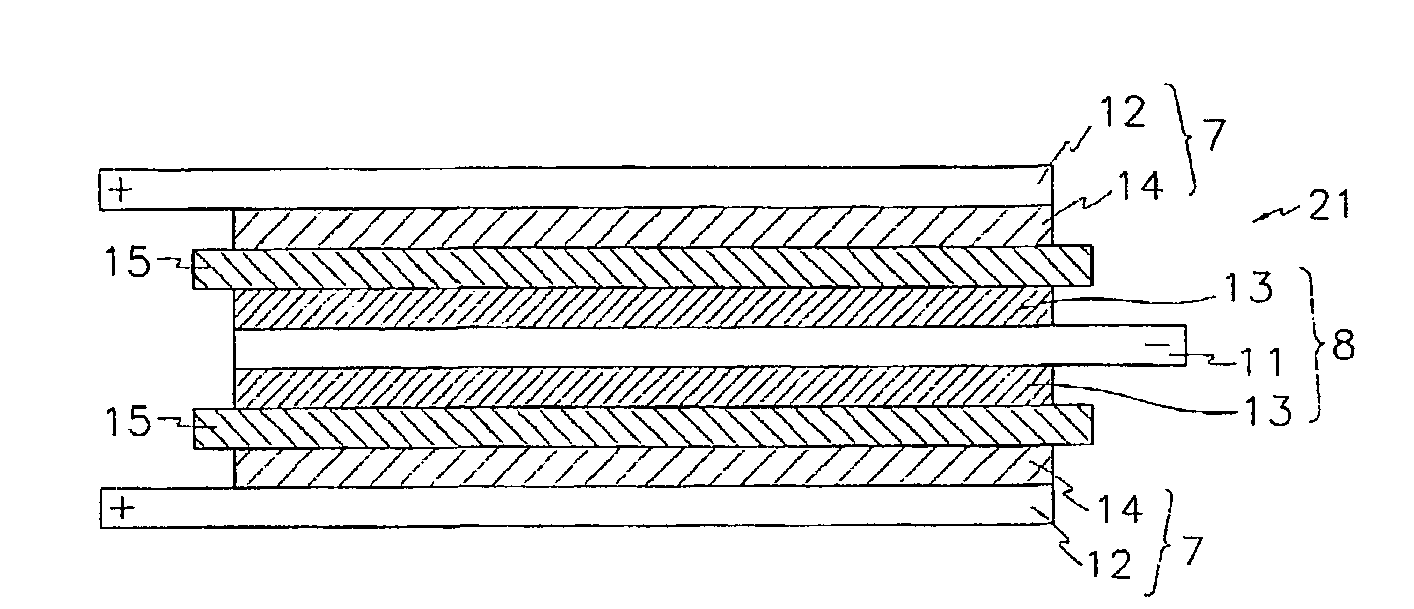
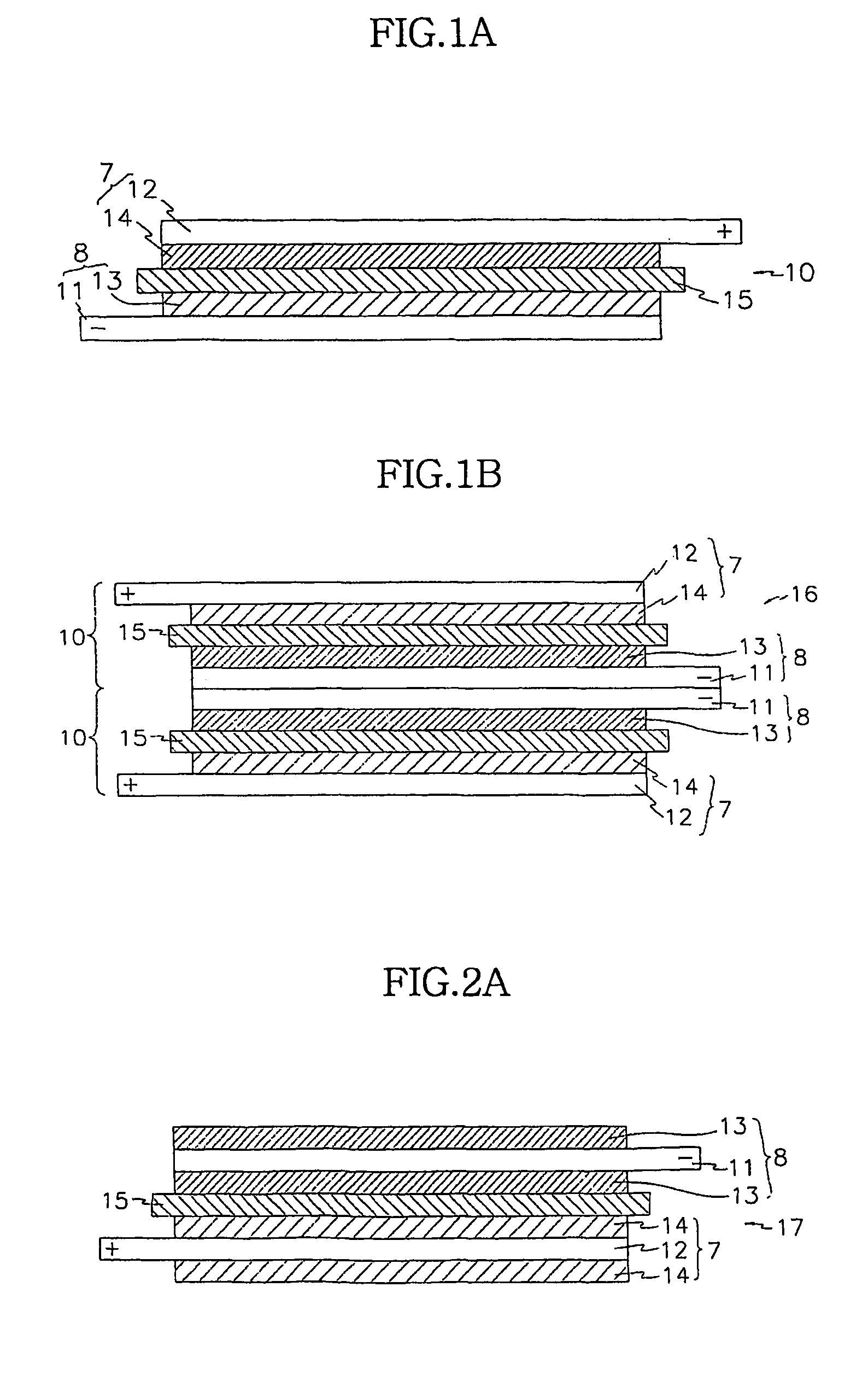
Preparing a Stacked Cell where a Fuel Cell is a Basic Unit

[0116](Preparing Positive Electrodes)

[0117]LiCoO2, carbon black, and PVDF, of which the weight ratio was 95:2.5:2.5, were dispersed in 1-methyl-2-pyrrolidone (NMP) in order to prepare a slurry. The slurry was then coated on aluminum foil on both sides of the aluminum foil. After sufficiently drying at 130° C.; the positive electrodes were prepared by pressing. The thickness of the positive electrode was 115 μm.

[0118](Preparing an Negative Electrode)

[0119]Graphite: acetylene black: PVDF, of which the weight ratio was 93:1:6, were dispersed in NMP in order to prepare a slurry The slurry was then coated on a copper foil on both sides of the copper. After sufficiently drying at 130° C., the negative electrodes were prepared by pressing. The thickness of the negative electrode was 120 μm.

[0120](Preparing a Multi-Component Composite Film)

[0121]A high crystalline polypropylene was used for a material of a precursor film. It had a me...

example 2

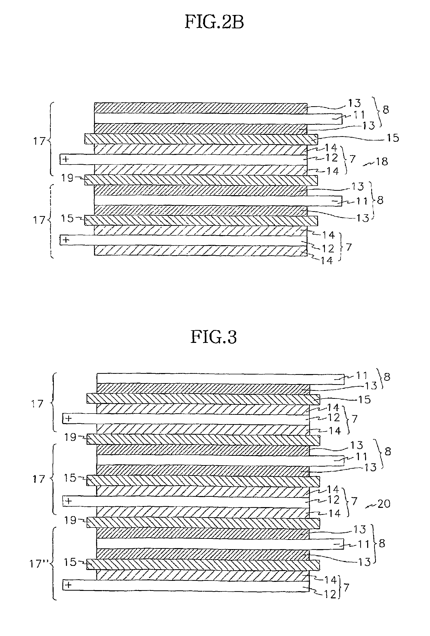
Preparing a Stacked Cell where a Bicell is a Basic Unit

[0138](Preparing a Positive Electrode)

[0139]Each positive electrode was prepared according to the same method as in the above Example 1.

[0140]A positive electrode of the bicell that was to be placed in the inner side was prepared by coating the slurry on both sides of aluminum foil. That is, the positive electrode has a positive active material coated on both sides of the aluminum positive current collector. The thickness of the positive electrodes was 140 μm.

[0141](Preparing an Negative Electrode)

[0142]Each negative electrode was prepared was prepared according to the same method as in the above Example 1.

[0143]Negative electrodes that were to be placed in the outermost sides of the outermost fuel cells were prepared by coating the slurry and on both sides of copper negative current collectors, and negative electrodes that were to be placed in the inner side were prepared by coating the slurry on both sides of copper negative c...


PUM

PropertyMeasurementUnit
thicknessaaaaaaaaaa
thicknessaaaaaaaaaa
thicknessaaaaaaaaaa

Abstract

The present invention provides a electrochemical element, wherein a multi-component composite film comprising a) polymer support layer film and b) a porous gellable polymer layer which is formed on either or both sides of the support layer film of a), wherein the support layer film of a) and the gellable polymer layer of b) are unified with each other without an interface between them.

Description

CROSS REFERENCE TO RELATED APPLICATION[0001]This application is the national phase under 35 U.S.C. § 371 of PCT International Application No. PCT / KR02 / 00377 which has an International filing date of Mar. 5, 2002, which designated the United States of America.BACKGROUND OF THE INVENTION[0002](a) Field of the Invention[0003]The present invention relates to an electrochemical element, and particularly, to an electrochemical element with improved energy density comprising multiply-stacked electrochemical cells using multi-component composite films, wherein the multi-component composite films are attached without forming an interface between a support layer film and a porous gellable polymer layer.[0004](b) Description of the Related Art[0005]There has been growing interest in energy storage technology. The applicable field of the battery has been expanded to cellular phones, camcorders, and notebook computers, and electric vehicles have recently been added to this list. Such expansion h...

Claims


Application Information

Patent Timeline
Patent Type & Authority Patents(United States)
IPC IPC(8): H01M2/16C08K3/10B01D67/00B01D69/12C08K3/22C08L101/00H01M6/22H01M8/02H01M8/10H01M10/05H01M10/0567H01M10/0568H01M50/417H01M50/42H01M50/423H01M50/426H01M50/491
CPCB01D67/0013B01D67/0083B01D67/009B01D69/12H01M2/14B01D67/0027H01M10/0565H01M10/0585H01M2/1653H01M10/0525B01D2325/04B01D2325/26Y02E60/10H01M50/417H01M50/491H01M50/42H01M50/423H01M50/426H01M50/449H01M4/131H01M4/133B01D69/1213B01D69/1216
Inventor LEE, SEUNG-JINLEE, HYANG-MOKAHN, SOON-HOCHO, JIN-YEONYONG, HYUN-HANGLEE, HYUNG-KEUNLEE, SANG-YOUNGSONG, HEON-SIKAHN, BYEONG-INPARK, SOON-YONGKYUNG, YOU-JIN
Owner TORAY BATTERY SEPARATOR FILM
Why Eureka
Try Eureka