Methods for forming metal parts having superior surface characteristics

a technology of surface characteristics and metal parts, applied in the field of forming metal products, can solve the problems of failure of parts, parts subject to other deformation, alteration of airfoil section dimensions, etc., and achieve the effect of superior surface characteristics

Inactive Publication Date: 2006-05-16
RECAST AIRFOIL GROUP
View PDF14 Cites 41 Cited by
  • Summary
  • Abstract
  • Description
  • Claims
  • Application Information

AI Technical Summary

Benefits of technology

[0034]The present invention overcome the drawbacks of the conventional art for repairing gas turbine engine airfoil parts. It is an object of the present invention to provide a method forming...

Problems solved by technology

These deforming stresses cause creep rupture and fatigue problems that can result in the failure of the part.
However, like the rotating parts, these parts are subjected to other deformation such as from hot gas erosion and/or foreign particle strikes.
This deformation results in the alteration of the dimensions of the airfoil section.
The alteration of the dimensions of the airfoil section can detrimentally modify the airflow through the gas turbine engine which is critical to the engine's performance.
The repair operations that remove metal by chemical stripping, grit blasting, blending and polishing shorten the life cycle of the vane.
When certain minimum airfoil dimensions cannot be met the part is deemed non-repairable and must be retired from service.
During use, the coating at the cutting surface of the cutting tool is subjected to shearing forces resulting in flaking of the coating off the tool substrate.
The failure is likely to occur at the narrow bonding interface.
Since the coating adheres to the tool bit substrate mostly via a mechanical bond located at a boundary interface, flaking and chipping off the coating off of the substrate is likely to occur during use, limiting the service life of the tool bit.
During extended use the tool bit is likely to fail at the relatively brittle brazed interface between the metal cutting tip and the tool substrate, and again, the useful service life of the tool bit is limited.
A cast metal component will typically have a number of imperfections caused by voids and contaminants in the cast surface structure.
The manufacture of metal components often entails costly operations to produce products with the desired surface textu...

Method used


Image

  • Methods for forming metal parts having superior surface characteristics
  • Methods for forming metal parts having superior surface characteristics
  • Methods for forming metal parts having superior surface characteristics

Examples


Embodiment Construction

[0090]For purposes of promoting an understanding of the principles of the invention, reference will now be made to the embodiments illustrated in the drawings and specific language will be used to describe the same. It will nevertheless be understood that no limitation of the scope of the invention is thereby intended, there being contemplated such alterations and modifications of the illustrated device, and such further applications of the principles of the invention as disclosed herein, as would normally occur to one skilled in the art to which the invention pertains.

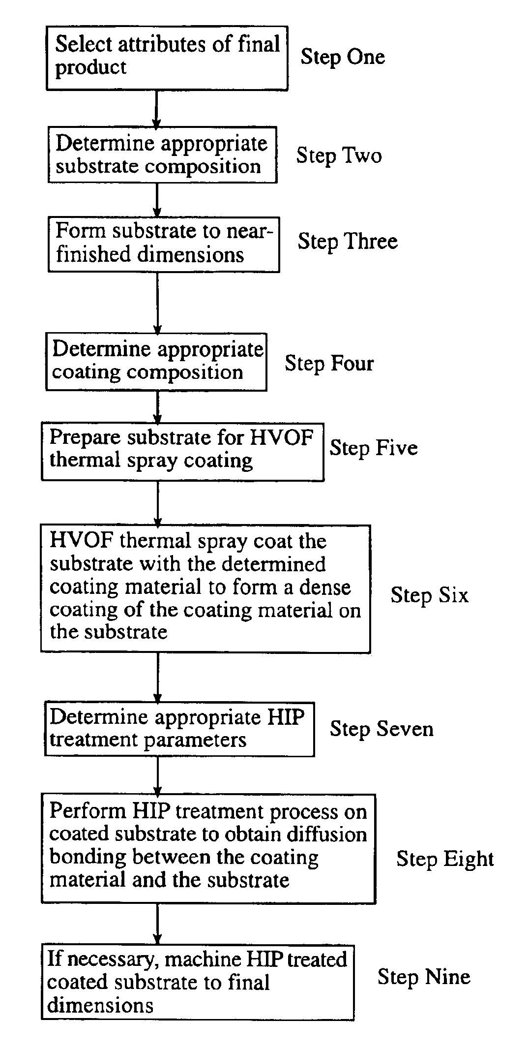
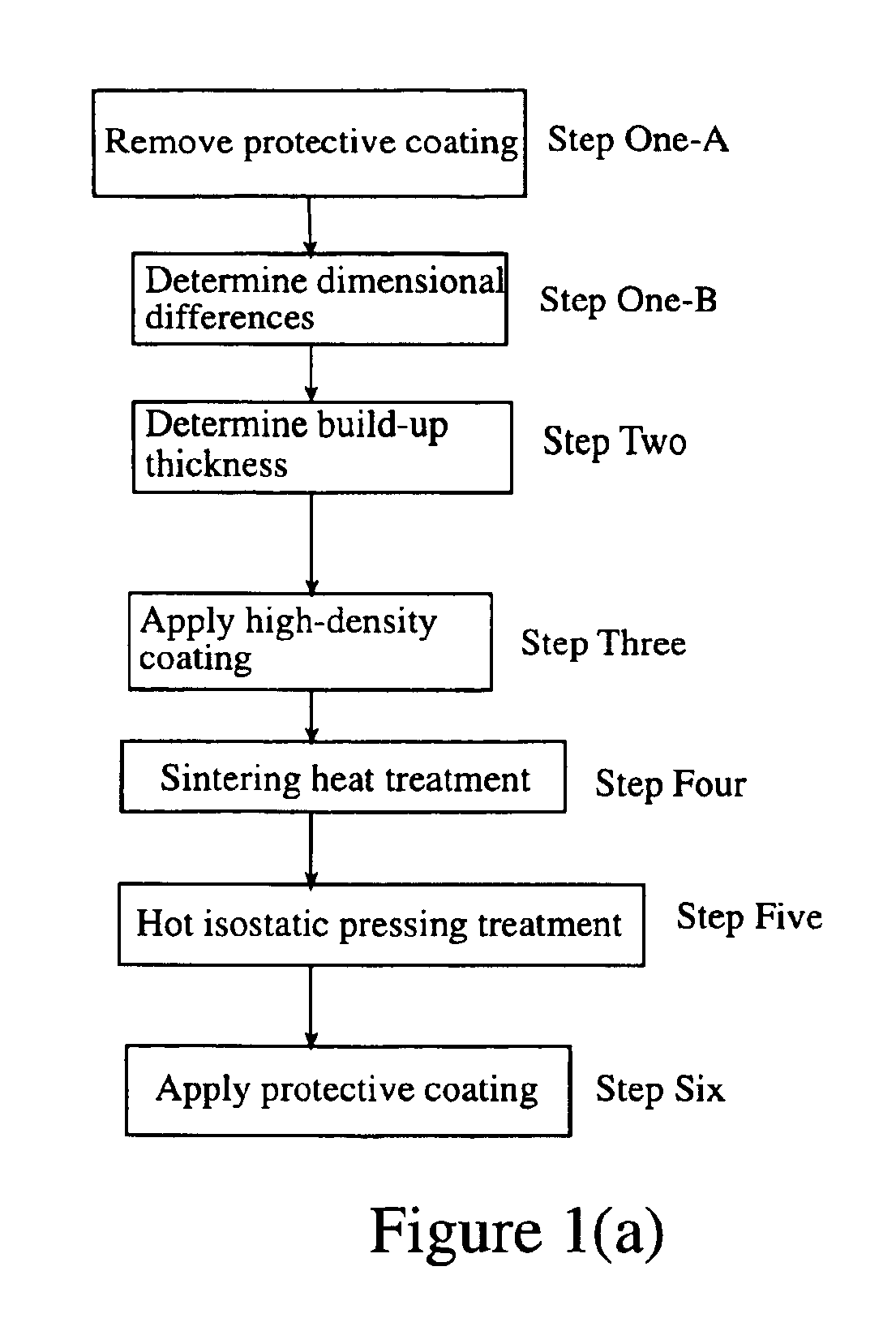
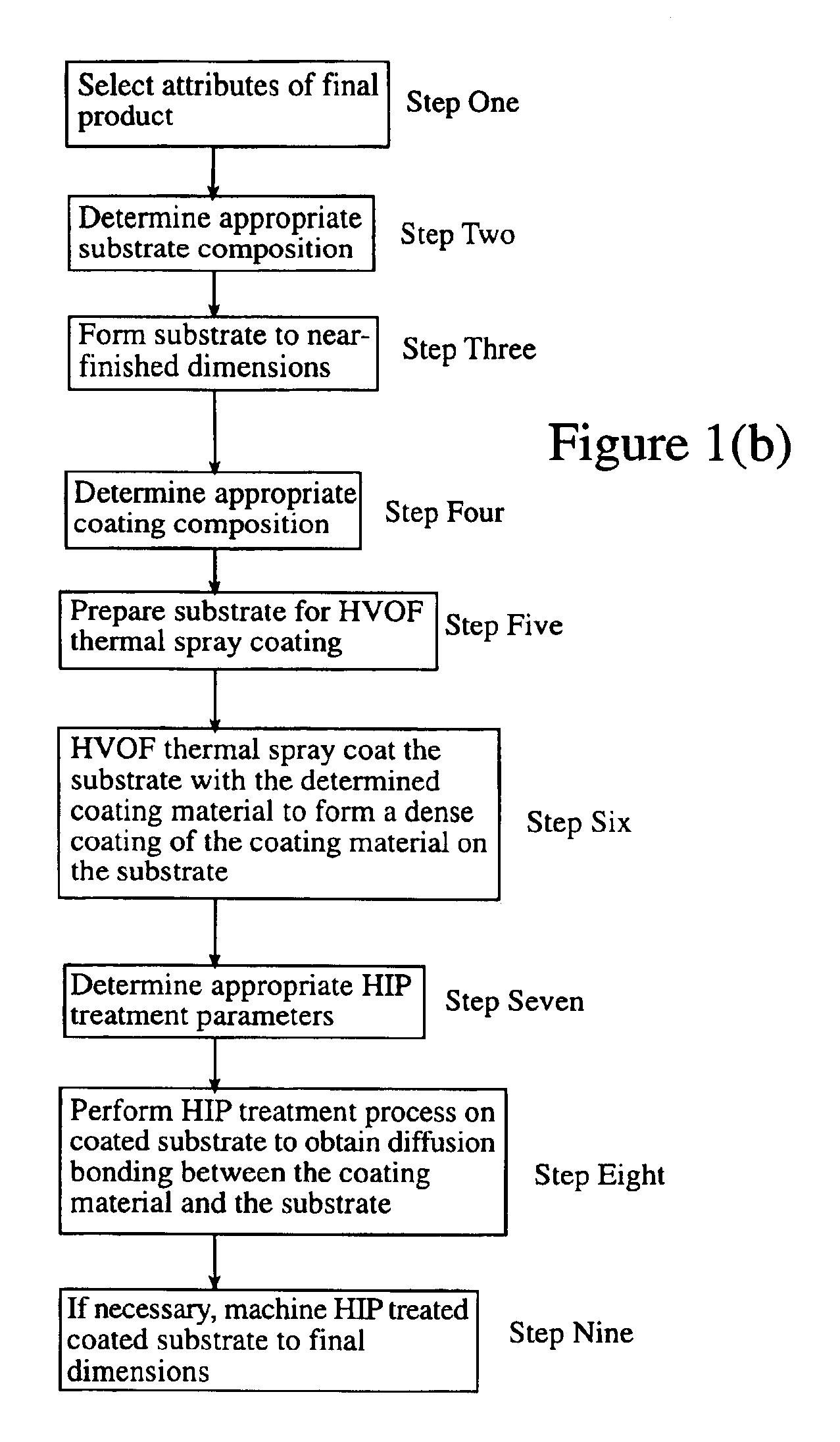
[0091]Referring to FIG. 1(a), in accordance with the present invention, the dimensional differences between pre-repaired dimensions of a turbine engine airfoil part and desired post-repair dimensions of the turbine engine airfoil part are determined (Step One-B). The turbine engine airfoil part has a substrate comprised of a superalloy. A build-up thickness of coating material required to obtain the desired post-repai...


PUM

PropertyMeasurementUnit
Fractionaaaaaaaaaa
Fractionaaaaaaaaaa
Fractionaaaaaaaaaa

Abstract

A method of forming a metal product. A metal alloy workpiece substrate is provided have pre-process dimensions. The dimensional differences are determined between the pre-process dimensions of the workpiece substrate and desired post-process dimensions of a post-process metal product formed from the workpiece substrate. A build-up thickness is determined of coating material required to obtain the desired post-process dimensions of the post-process metal product. A high-density coating process is performed to coat the workpiece substrate with a coating material to build-up a thickness of coating material effective to obtain desired finished dimensions after performing a sintering heat treatment process and/or a hot isostatic pressing treatment. The sintering heat treatment is performed on the coated workpiece substrate to densify the coating material. Then, the hot isostatic pressing treatment is performed to obtain the post-process metal product having the desired post-process dimensions and having diffusion bonding between the coating material and the workpiece substrate.

Description

CROSS-REFERENCE TO RELATED APPLICATIONS[0001]The present application is a Continuation-in-Part of application Ser. No. 09 / 143,643, filed Sep. 3, 1998, now U.S. Pat. No. 6,049,978, which is a Continuation-in-Part of application Ser. No. 08 / 993,116 filed Dec. 18, 1997, now U.S. Pat. No. 5,956,845, which is the utility patent application of a U.S. provisional application Ser. No. 60 / 033,858, filed Dec. 23, 1996; and relates to an invention disclosed in an Invention Disclosure Document accepted under the Disclosure Document program on or about Nov. 5, 1996 and assigned Disclosure Document No. 407616.BACKGROUND OF THE INVENTION[0002]The present invention pertains to a method for forming metal products. More particularly, the present invention pertains to a method for forming metal products having superior surface charateristics.[0003]Airfoil parts, such as blades and vanes, are critical components in the gas turbine engines that are used to powerjet aircraft or for the generation of elec...

Claims


Application Information

Patent Timeline
IPC IPC(8): B23P15/00
CPCB23P6/007C23C4/18C23C26/00F01D5/288C23C30/005F05D2230/90Y02T50/672Y10T29/49982Y02T50/60
Inventor ARNOLD, JAMES E.
Owner RECAST AIRFOIL GROUP
Why Eureka
Try Eureka