Extreme ultraviolet light source

a technology of ultraviolet light and ultraviolet light, which is applied in the field of extreme ultraviolet light source devices, can solve the problems of difficult plasma conversion of all of the target b>22/b>, difficult laser irradiation, and damage to the nozzle b>21/b>, and achieves the effects of extreme ultraviolet light, increased working distance, and high outpu

Inactive Publication Date: 2006-06-27
GIGAPHOTON
View PDF6 Cites 41 Cited by
  • Summary
  • Abstract
  • Description
  • Claims
  • Application Information

AI Technical Summary

Benefits of technology

[0062]The present invention was devised in light of abovementioned problems; it is an object of the present invention to provide an extreme u

Problems solved by technology

However, since Be is very toxic, the realization of an extreme ultraviolet light source with a high brightness in the vicinity of 13 to 14 nm where a high reflectivity is obtained in an Mo/Si multi-layer film is desired.
However, when the target 22 is a solid, it is difficult to convert all of the target 22 into a plasma.
However, the problems described in 5.1 through 5.6 below are encountered in abovementioned liquid filament system.
5.1 Hydrodynamic instability such as hose instability and the like resulting from the continuous jetting of a

Method used


Image

  • Extreme ultraviolet light source
  • Extreme ultraviolet light source
  • Extreme ultraviolet light source

Examples


first embodiment

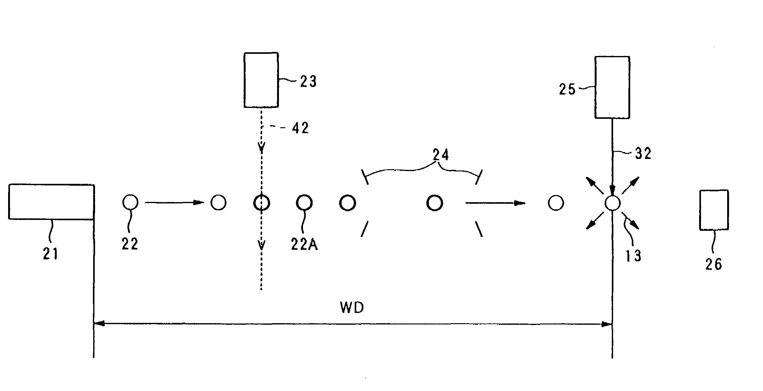
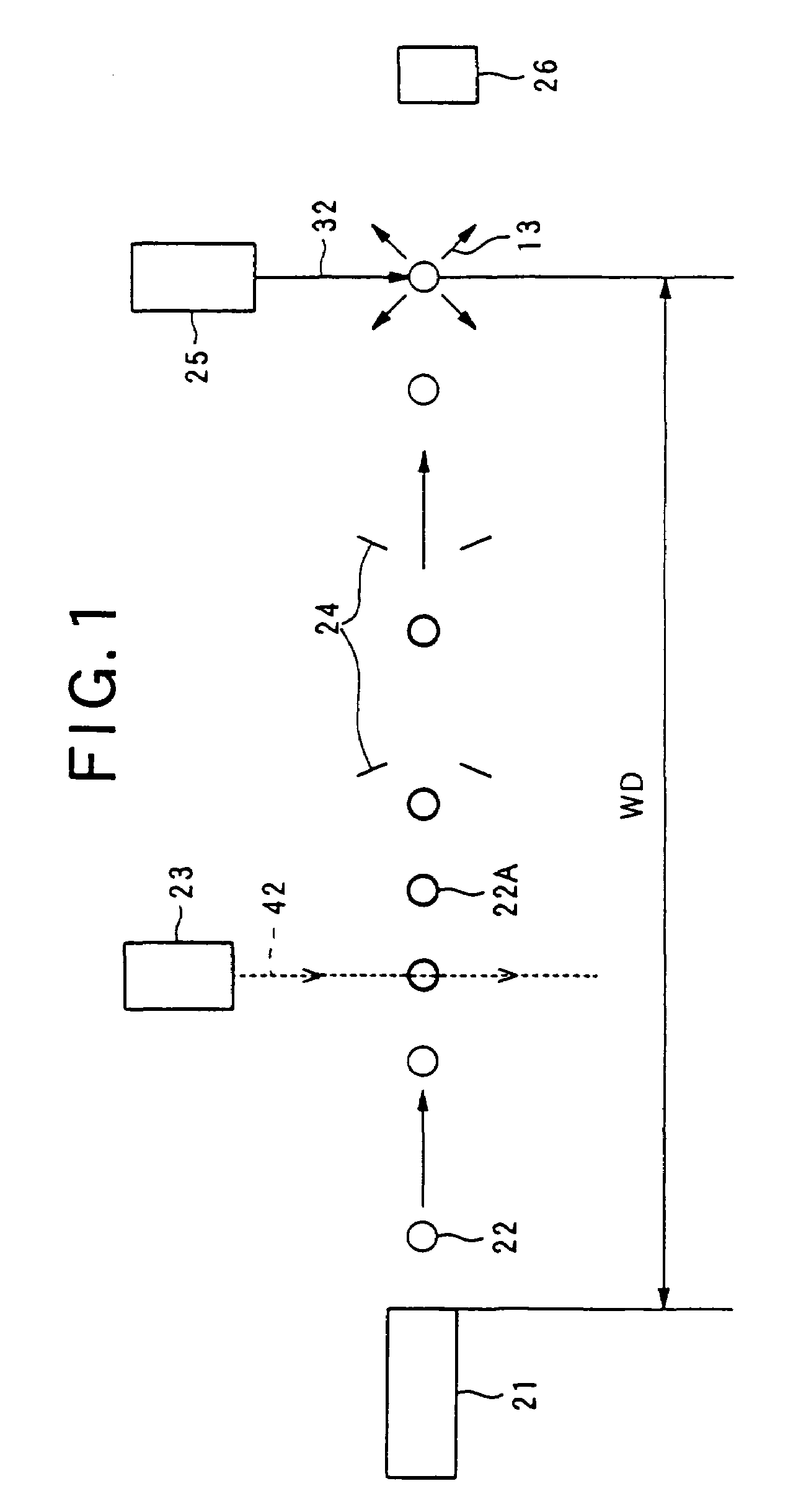
[0103]FIG. 1 shows a structural diagram of an extreme ultraviolet light source device 11 of a

[0104]For example, a piezoelectric element or the like (not shown in the figures) is disposed inside a nozzle 21 that supplies the target 22, so that the target 22 can be caused to jet at a high velocity. The target 22, which is liquefied by cooling means (not shown in the figures), is emitted from the nozzle 21, and is charged by irradiation with an electron beam 42 generated by an electron beam generator 23 while the target is traveling at the emission velocity. The material of the target 22 is liquid Xe, solid Xe, or some other liquid or solid substance. If an electron beam 42 with a diameter of approximately 100 μm is used on a target 22 with a diameter of approximately 10 μm, the entire target 22 can be irradiated by the electron beam 42.

[0105]The traveling velocity of the charged target 22A is accelerated by (for example) a van de Graaff type accelerating device 24, and is subsequently...

second embodiment

[0124]Next, a second embodiment will be described.

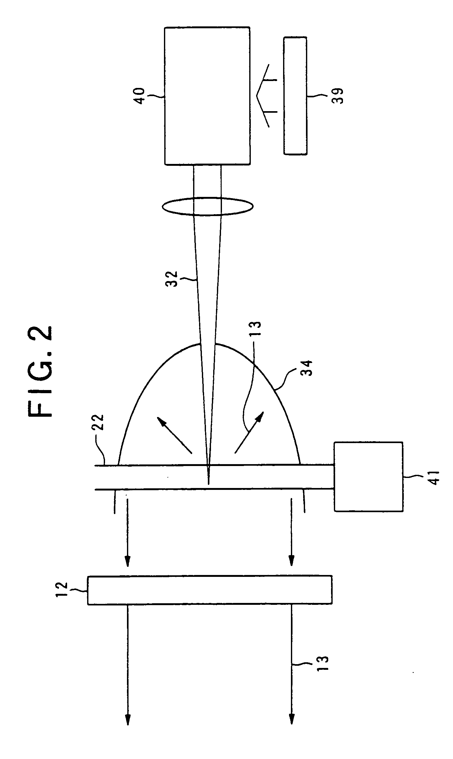
[0125]In the second embodiment, a carbon dioxide gas laser device with a 10 μm wavelength band is used as the driving laser device 25. The laser light is focused by an irradiation optical system on the flow path of a gas-form target 22 that is separated from the nozzle 21 by a distance of several centimeters to several tens of centimeters, so that a plasma is generated.

[0126]The plasma that is thus generated has a length of several millimeters to several centimeters. The optical axis of the focusing optical system is caused to coincide substantially with the long axis of the plasma generated on this filament, and the EUV light generated from the plasma is focused so that this EUV light is focused and transmitted to the illumination optical system 14. In this case, the light passes through the debris shield 12 so that debris is removed, and so that only the extreme ultraviolet light 13 is emitted into the illumination optical system 1...

embodiment 3

[0136]Embodiment 3 has a construction that is substantially similar to that described above; in this embodiment, the amplification stage lasers are constructed from TEA-CO2 lasers. In this case, the following merit is obtained: namely, the pulse energy can be increased to a greater value than in a case where abovementioned amplification stage lasers are constructed from CW-CO2 lasers.

[0137]In the present invention, as was described above, the target 22 can be controlled by applying a charge to clusters, or applying an electromagnetic field to a charged target 22 formed by ionizing gas molecules. Accordingly, the following effects are obtained:

[0138]6.1 A high-velocity flow of the target 22 can be generated by combining the present invention with a technique using an ion beam accelerating device 24.

[0139]6.2 The plasma generation point can be removed to a position that is distant from the nozzle 21. As a result, there is little damage to the nozzle 21, and design of the focusing opti...


PUM


Abstract

An extreme ultraviolet light source device which makes it possible to increase a working distance and obtain extreme ultraviolet light with a high output. The extreme ultraviolet light source device generates a plasma by irradiating a target (22) with laser light from a driving laser device (25), and generates extreme ultraviolet (EUV) light with a wavelength of several nanometers to several tens of nanometers. The extreme ultraviolet light source device comprises a target supply device which has a charge applying unit (23) that applies a charge to the target (22), and an acceleration unit (24) which accelerates the charged target (22) using an electromagnetic field. The target supply device supplies the target (22) comprised of a rare gas element such as xenon (Xe) or the like, or a metal such as lithium (Li), tin (Sn), tin oxide (SnO2) or the like, as ionized molecules, atoms or masses comprising a plurality of atoms, or as ionized clusters.

Description

TECHNICAL FIELD[0001]The present invention relates to an extreme ultraviolet light source device that is used as a light source in photolithography.BACKGROUND ART[0002]With the increasing fineness seen in semiconductor processes, there has also been a rapid increase in the fineness of photolithography. The early achievement of the schedule for increased fineness in the SIA roadmap has advanced year by year; this trend is accelerating, with an achievement one year ahead of schedule from the edition at the end of 1997 to the 1999 edition, and an achievement two years ahead of schedule in Scenario 2 of the 2000 edition. Accompanying this trend, there has been a yearly advance in the decrease of wavelengths of lithographic light sources. Specifically, beside the g line and i line of mercury lamps, exposure apparatuses that combine KrF excimer laser devices (λ=248 nm) or ArF excimer laser devices (λ=193 nm) with a refractive optical system (dioptric system) were used.[0003]There is curre...

Claims


Application Information

Patent Timeline
IPC IPC(8): G01J1/00G03F7/20G21K5/00G21K5/02G21K5/08H01L21/027H05G2/00
CPCB82Y10/00G03F7/70033H05G2/005H05G2/008H05G2/003
Inventor MIZOGUCHI, HAKARUENDO, AKIRATANAKA, HIROKAZU
Owner GIGAPHOTON
Why Eureka
Try Eureka