

Flexible imaging member belt seam smoothing method
a flexible imaging member and seam treatment technology, applied in the direction of driving belts, auxillary shaping apparatus, butter manufacture, etc., can solve the problems of dynamic fatigue seam cracking, welded seam cracking of charge transport layer at the welded seam area, and frequent encounter of fatigue induced cracking of the charge transport layer during photoreceptor belt cycling, etc., to reduce the thickness of the seam region, smooth out the seam, and eliminate the effect of protruding spots
- Summary
- Abstract
- Description
- Claims
- Application Information
AI Technical Summary
Benefits of technology
Problems solved by technology
Method used
Image

Examples
example i
[0079]An electrophotographic imaging member web was prepared by providing a roll of titanium coated biaxially oriented thermoplastic polyester (Melinex, available from ICI Americas Inc.) substrate having a thickness of 3 mils (76.2 micrometers) and applying thereto, using a gravure applicator, a solution containing 50 parts by weight 3-aminopropyltriethoxysilane, 50.2 parts by weight distilled water, 15 parts by weight acetic, 684.8 parts by weight of 200 proof denatured alcohol, and 200 parts by weight heptane. This layer was then dried to a maximum temperature of 290° F. (143.3° C.) in a forced air oven. The resulting blocking layer had a dry thickness of 0.05 micrometer.
[0080]An adhesive interface layer was then prepared by applying to the blocking layer a wet coating containing 5 percent by weight, based on the total weight of the solution, of polyester adhesive (Mor-Ester 49,000, available from Morton International, Inc.) in a 70:30 volume ratio mixture of tetrahydrofuran / cyclo...
example ii
[0086]The electrophotographic imaging member web of Example I having a width of 353 millimeters, was cut into four separate rectangular sheets of precise 559.5 millimeters in length. The opposite ends of each imaging member were overlapped 1 mm and joined by ultrasonic energy seam welding process using a 40 Khz horn frequency to form four seamed electrophotographic imaging member belts. Three of these seamed belts are to be subjected to a protrusion elimination process while the remaining untreated belt is used to serve as a control.
example iii
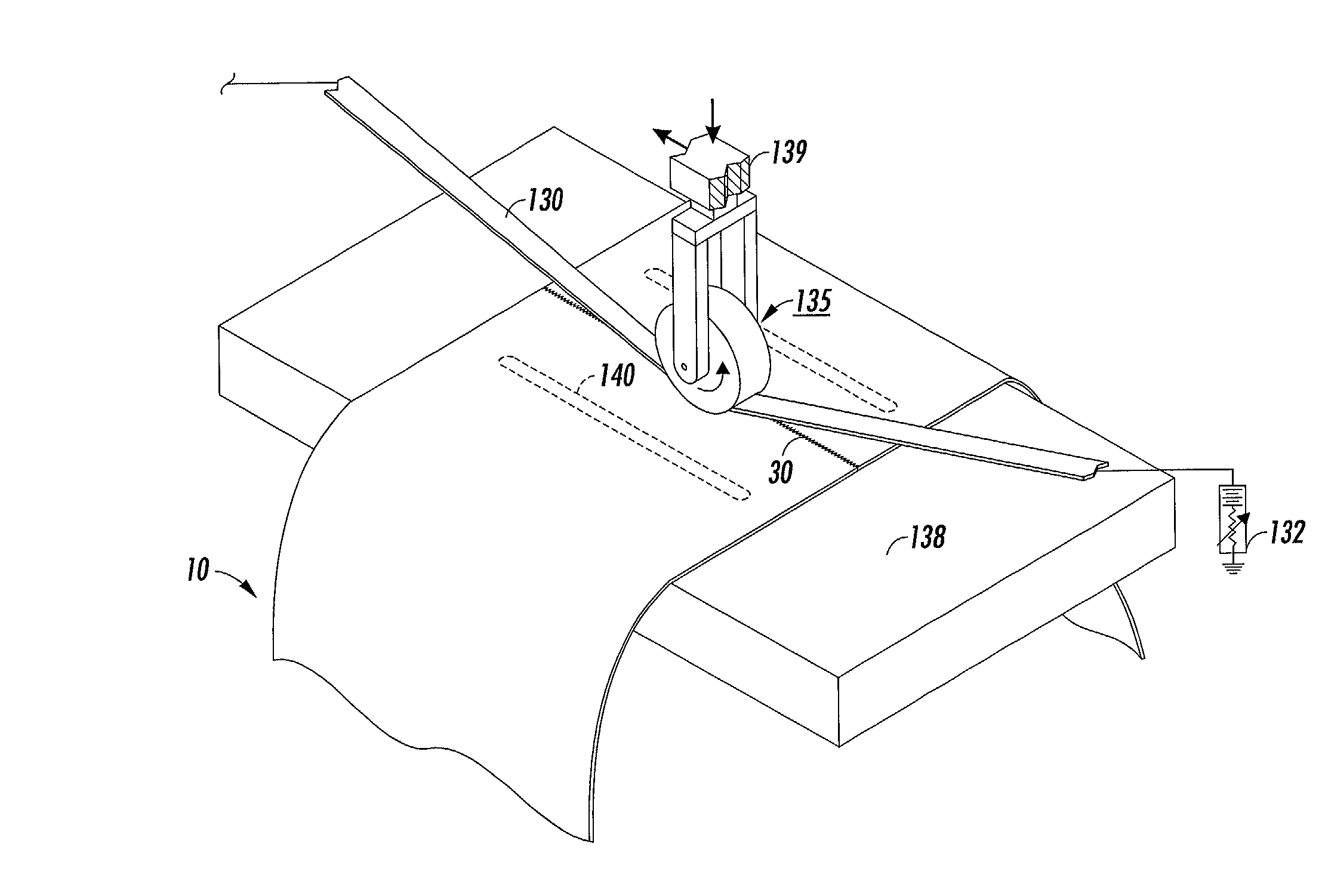
[0087]To effect seam treatment processing, each of the three welded electrophotographic imaging member belts described in Example II may be suspended and held down, with the seam in the middle, against a horizontally positioned elongated smooth flat surface support member by a pair of vacuum slot, each slot extending transversely across the width of the imaging member belt. Each slot may be 2 millimeters wide. The slots are connected to a vacuum source to provide and maintain a vacuum pressure of about 40 mm Hg. The belt in the seam region can be held down against the flat upper surface of the support member so when the valve to the vacuum source is opened the seam area conforms to the flat surface of the support member. A narrow, heated heating and compression bar having a contacting flat surface of about 12 millimeters in width and a length sufficient to match the full imaging member belt width can be used to press against the seam region to provide a 50 kilograms per square centi...
PUM
| Property | Measurement | Unit |
|---|---|---|
| width | aaaaa | aaaaa |
| width | aaaaa | aaaaa |
| temperature | aaaaa | aaaaa |
Abstract
Description
Claims
Application Information