Method and apparatus for chemical vapor deposition capable of preventing contamination and enhancing film growth rate

a technology of chemical vapor deposition and film growth rate, which is applied in the field of method and apparatus for chemical vapor deposition (cvd), can solve the problems of contaminating thin films while manufacturing, affecting the reliability of the manufacturing process, and generating undesired films or powders in the reaction chamber, etc., and achieves a remarkable enhancement of the film growth rate and the density of source material

Inactive Publication Date: 2007-01-02
EPPZ +1
View PDF23 Cites 22 Cited by
  • Summary
  • Abstract
  • Description
  • Claims
  • Application Information

AI Technical Summary

Benefits of technology

[0014]Accordingly, it is an object of the present invention to provide a method for CVD comprising steps of injecting a purge gas, which doesn't either dissolve or generate byproducts by itself, into a reaction chamber where substrates are placed introducing the purge gas into the inside of the reactive gas confining means having plural openings; and supplying a source material of vapor phase participating directly in forming a film on the substrates to an inside of the reaction chamber, thus forming a protective curtain in the inside of the reaction chamber by a mutual diffusion-suppressing action between the purge gas and source material. According to the method for CVD of the invention described above, it is possible to increase the density of source material substantially only in the vicinity of the substrates and enhance film growth rate remarkably.
[0016]Another object of the present invention is to provide the method for CVD described above, wherein the reactive gas confining means has a plurality of openings through which the purge is introduced to the inside of the reactive gas confining means, thus preventing the source material from diffusing to the outside of the reactive gas confining means, and forming a protective curtain that prevents the source material from touching the reactive gas confining means.
[0017]An additional object of the present invention is to provide the method for CVD described above, wherein an amount of the purge gas injected to the outside of the reactive gas confining means is set much larger than that of the source material supplied to the inside of the reactive gas confining means to direct the protective curtain of purge gas from the outside to the inside of the reactive gas confining means, thus preventing the source material from touching the reactive gas confining means.

Problems solved by technology

However, the reactive gas injected into the chamber 3 generates undesired films or powders on the reaction chamber components such as walls, reactive gas distributing showerheads, substrate heating devices, inspection windows, etc.
Moreover, the undesired films and / or powders formed on the reaction chamber components are broken to be small particles by repeated thermal expansion / contraction and / or lattice parameter mismatch between the reaction chamber components, thus contaminating the thin films while manufacturing.
Here, if the number of the contaminant particles in the chamber 3 is increased, the reliability of the manufacturing process is deteriorated seriously.
For example, in case of making very large scale integration (VLSI), the contaminant particles result in serious pattern inferiority such as circuit short.
Meanwhile, to enhance film growth rates in the conventional CVD system, it is necessary to increase the density of the reactive gas in the vicinity of the susceptor by adding the reactive gas to all space of the chamber 3 in practice, which requires the amount of the reactive gas excessively, thus deteriorating the economic efficiency.
However, the range of the temperature regulatable is very narrow, and furthermore, if the reactive gas is composed of several source materials, the range of temperature to regulate doesn't exist actually.
Consequently, it is impossible to prevent generation of contaminant particles by regulating the reaction chamber temperature.
Besides, in the conventional CVD system, the temperature difference between the inner wall of the chamber 3 and the susceptor 5 causes a natural convection, which makes it difficult to maintain the diffusion of the reactive gas uniformly onto the substrates, thus deteriorating the reliability of the films formed.
Moreover, the natural convection makes the contaminant particles generated continue to re-circulate in the chamber, which aggravates the problem of the contamination.
However, it seems that relaxation of the contamination is done only at the limited portion of the whole reaction chamber in both prior arts cited.
In FIG. 2, there exists an unavoidable re-circulation zone near the leading edge of the substrate, and it is difficult to suppress the diffusion of the reactive gas to the chamber wall, which deteriorates the effectiveness of the reference system.
Moreover, the external control of purge gas flow rate may need much trial to make the reactive gas flow stabilized, since the laminar flow zone of the reactive gas is very narrow while the purge gas suppresses the narrow zone overall perpendicularly, thereby involving the latent instability of the flow.
In FIG. 3, although the purge gas control system may be effective in preventing deposits on the window of the lamp system, it is not sure whether the reference apparatus could prevent particles being formed on the surface of the reaction chamber components such as chamber walls, especially around the areas far away from the purge gas showerhead.
This problem would become serious when long process time and / or high growth rate is required.

Method used


Image

  • Method and apparatus for chemical vapor deposition capable of preventing contamination and enhancing film growth rate
  • Method and apparatus for chemical vapor deposition capable of preventing contamination and enhancing film growth rate
  • Method and apparatus for chemical vapor deposition capable of preventing contamination and enhancing film growth rate

Examples


example 1

Configuration of CVD Apparatus

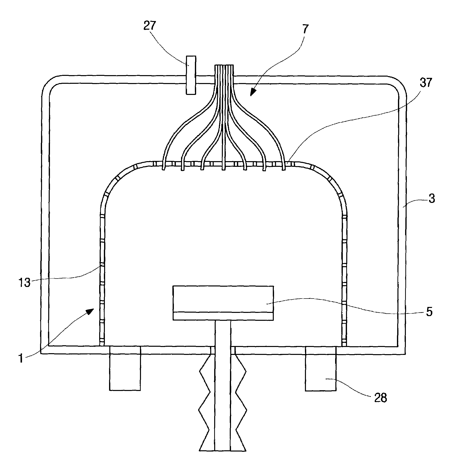
[0064]In a preferred embodiment in accordance with the present invention, as shown in FIG. 7, the reactive gas confining means 1 having a diameter of 300 mm and a height of 445 mm was provided to surround the susceptor 5, having a diameter of 240 mm and a height of 80 mm, positioned in the midst of the reaction chamber 3. The means 1 employed has a funnel-like shape through which the purge gas is diffused to the inside of the means 1. The reactive gas supply ports 7 were equipped on the top of the means 1 and the purge gas supply port 9 provided over the means 1.

example 2

TiO2 Film Deposition

[0065]TiO2 film deposition was made using the CVD apparatus described in Example 1. Following equation denotes TiO2 film deposition by TIP pyrolysis.

Ti(OC3H7)4→TiO2(s)+4C3H6+2H2O

[0066]Titanium iso-propoxide (TIP, Ti(OC3H7)4) was employed as a precursor for TiO2 film deposition. The vapor pressure of TIP was 2 Torr at 70° C. The heating temperature of TIP was 85° C., and the reaction chamber pressure was 133 Pa. Pure TIP gas was supplied to the inside of the means 1 at a flow rate of 1×10⁻⁶ kg / sec without the aid of carrier gas, whereas Argon as purge gas was injected into the outside of the means 1 at a flow rate of 10×10−6 kg / sec. At appropriately low heating temperatures, i.e., at the range from 70° C. to 100° C., TIP can be easily vaporized but hardly decomposed in the TIP container. Pure vapor of TIP can be delivered without the aid of carrier gas into the chamber 3 where the chamber pressure is much lower than the TIP vapor pressure. Here, there is an advant...

example 3

[0067]As shown in FIG. 17, TiO2 film deposition was made at various heights of the susceptor from the bottom of the means 1 with the CVD apparatus and conditions described in Examples 1 and 2, respectively, while keeping the uniformity of the deposition within ±5% in the range less than 100 mm in radial position. It was understood that the reason why the film growth rate beyond the radial position 100 mm, i.e., the edge portion of the upper surface of the susceptor, is increased steeply is because the velocity vector is abruptly changed in this vicinity.


PUM

PropertyMeasurementUnit
thicknessaaaaaaaaaa
diameteraaaaaaaaaa
diameteraaaaaaaaaa

Abstract

Disclosed relates to a method for CVD comprises steps of injecting a purge gas, which doesn't either dissolve or generate byproducts by itself, into a reaction chamber where substrates are located; and supplying a source material of vapor phase participating directly in forming a film on the substrates to an inside of the reaction chamber, thus forming a protective curtain in the inside of the reaction chamber by a mutual diffusion-suppressing action between the purge gas and source material. Besides, the invention provides an apparatus for CVD including a susceptor located in a reaction chamber producing a vacuum, on which substrates are placed and a film deposition process is made, the apparatus comprising: a reactive gas confining means, established over the susceptor, having at least a source material supply port through which a source material is supplied and a plurality of openings perforated on a surface thereof; a purge gas supply port through which a purge gas is fed into an outside of the reactive gas confining means; and an exhaust port for discharging exhaust gasses generated in the reaction chamber.

Description

BACKGROUND OF THE INVENTION[0001]1. Field of the Invention[0002]The present invention relates in general to a method and apparatus for chemical vapor deposition (CVD), and more particularly to a method and apparatus for CVD that prevents contamination and enhancing film growth rate by directing a reactive gas for forming a film to the midst of a reaction chamber, and concentrating the reactive gas diffused over a susceptor in the chamber to prevent the reactive gas from being touching components of the reaction chamber.[0003]2. Description of the Related Art[0004]Chemical vapor deposition (CVD) is a thin film deposition process for forming solid material over the surface of a substrate using a reactant (usually in the form of gas, i.e., a reactive gas). As depicted in FIG. 1, a conventional apparatus for CVD comprises in general a reaction chamber 3 producing a vacuum, an inlet 7 for supplying the reactive gas to the chamber 3, a heating means 44 for chemically reacting the reactive...

Claims


Application Information

Patent Timeline
Patent Type & Authority Patents(United States)
IPC IPC(8): C23C14/56C23F1/08C23C16/44C23C16/455H01L21/31
CPCB82Y10/00B82Y30/00C23C16/45591C23C16/45519C23C16/4401
Inventor BYUN, CHULSOO
Owner EPPZ
Why Eureka
Try Eureka