Low expansion metal-ceramic composite bodies, and methods for making same

a technology low coefficient, which is applied in the field of metal-ceramic composite bodies, can solve the problems of inability to achieve sufficient fiber loading, and achieve the effect of low expansion, tougher and/or more impact resistan

Inactive Publication Date: 2007-01-30
II VI DELAWARE INC
View PDF24 Cites 31 Cited by
  • Summary
  • Abstract
  • Description
  • Claims
  • Application Information

AI Technical Summary

Benefits of technology

[0025]It is an object of this invention to produce low expansion composite materials that are tougher and / or more impact resistant that glass matrix composites.
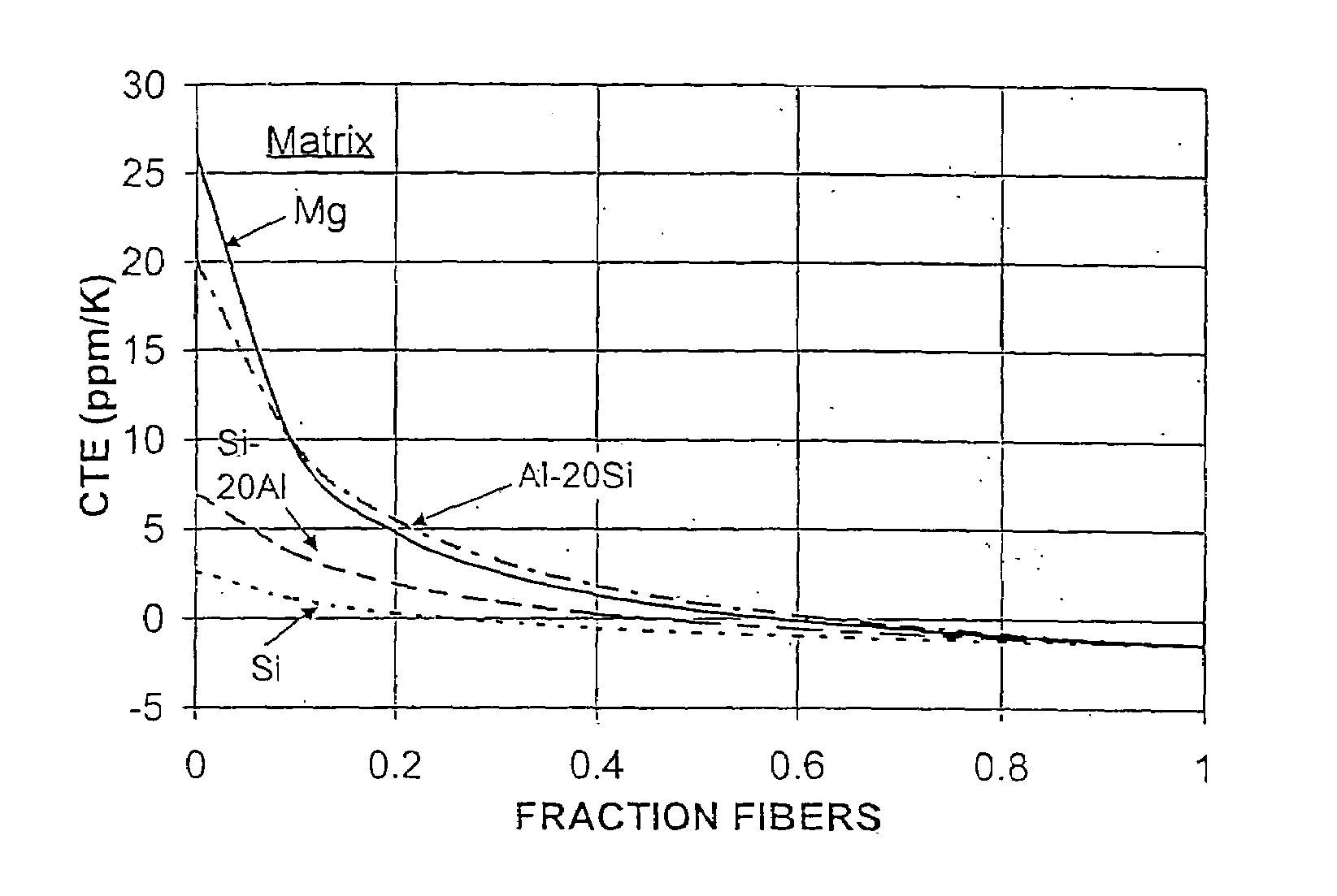
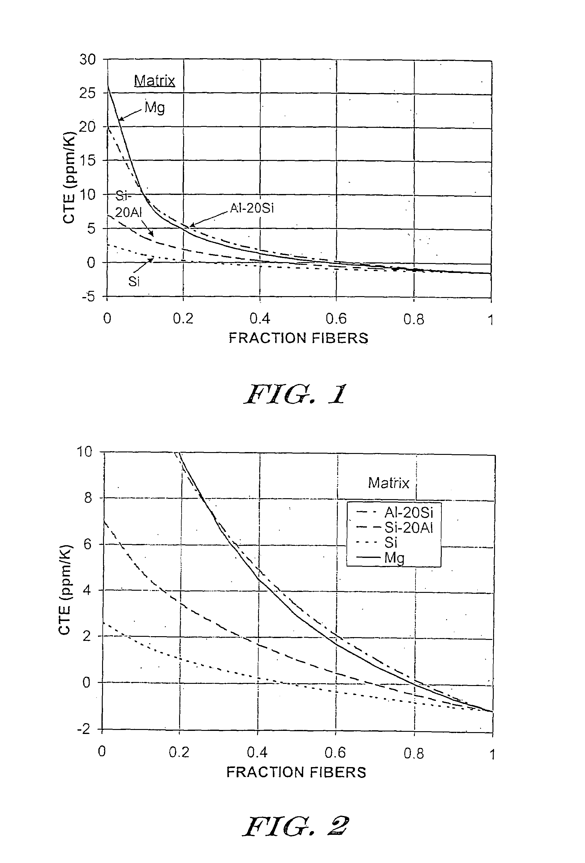
[0026]These and other objects of the present invention are achieved by reinforcing a lightweight matrix comprising one or more metals or semimetals such as aluminum, magnesium, copper, silicon or one of their alloys, with a reinforcement material possessing a negative CTE. Among the materials having such a property are certain fibers, wherein the fiber has a negative CTE in the axial direction, i.e., parallel to the fiber axis. Because the CTE of the matrix is positive while that of the fibers is negative, the individual contributing CTE's tend to cancel one another. Because of this counterbalancing or offset effect, it is theoretically possible to engineer a metal matrix composite material, or a composite material of any matrix, for that matter, to have a net overall CTE of zero.

Problems solved by technology

Given the high CTE and elastic modulus of some candidate matrix metals, it is for all practical purposes impossible to achieve sufficiently high fiber loadings to counterbalance this “adverse influence” of such matrix metals, in spite of the fact that the negative CTE fibers usually also possess very high elastic modulus.

Method used


Image

  • Low expansion metal-ceramic composite bodies, and methods for making same
  • Low expansion metal-ceramic composite bodies, and methods for making same
  • Low expansion metal-ceramic composite bodies, and methods for making same

Examples


example i

[0083]This example demonstrates how a high modulus graphite fiber reinforced magnesium composite might be produced according to the present invention.

[0084]Plies of parallel graphite fibers are supplied as “prepregs.”

[0085]In accordance with the teachings of U.S. Pat. No. 3,888,661 to Levitt, the plies are then “dusted” with titanium metal particulate having an average particle size of about 44 microns. During subsequent processing, the titanium will help the magnesium to wet and bond to the graphite fibers. In addition, as the fiber plies are assembled, each ply is “salted” with a layer of magnesium filings.

[0086]The plies are then arranged quasi-isotropically in a refractory mold. In particular, if the orientation of the first ply is taken to be 0°, then the second ply is placed flat on top of the first ply such that it is oriented +45° with respect to the first ply. The third ply is then placed flat on top of the second ply and oriented −45° with respect to the first ply. The fou...

example ii

[0090]The procedures of Example 1 are repeated, except that the teachings of U.S. Pat. No. 4,056,874 to Kalnin should obviate the need for adding magnesium filings and titanium particulate wetting agent between the fiber plies. Instead, about 5 to 10 percent by weight of magnesium nitride is added to the magnesium melt, thereby permitting the molten magnesium to wet and infiltrate the carbon fibers on contact in a gaseous nitrogen atmosphere. Such a melt can be obtained by exposing a crucible of molten magnesium at a temperature of about 840 to 850° C. to an atmosphere of gaseous nitrogen for about 40 minutes. Magnesium nitride solid will form on the surface of the melt, and this reaction product then may be readily dispersed in the magnesium melt.

example iii

[0091]A quasi-isotropic lay-up is assembled as in Example 1, but without the magnesium filings or titanium particulate. After removing the temporary binder, a protective coating of silicon carbide is deposited onto the graphite fibers, for example, by chemical vapor deposition, thereby completing the lay-up. The lay-up is placed into a vacuum furnace. The furnace chamber is evacuated to less than about 100 millitorr, and heated to a temperature of about 1300° C. Upon contacting the coated fibers with a matrix metal comprising about Si-50Al, the molten metal is spontaneously wicked into the mass of coated fibers to form a composite body.


PUM

PropertyMeasurementUnit
elastic modulusaaaaaaaaaa
angleaaaaaaaaaa
angleaaaaaaaaaa

Abstract

A low CTE metal-ceramic composite material featuring carbon fibers reinforcing a matrix featuring silicon metal or silicon alloy. The fibers have a low coefficient of thermal expansion (CTE) in the axial direction, and preferably negative. The principles of making Si/SiC composites can be adapted to produce the instant Si matrix composites. The CTE of the composite body depends not only upon the relative CTE's of the fibers and matrix, and their relative amounts (e.g., loadings), but also upon the relative elastic moduli of the fibers and matrix. Thus, Si/SiC matrices produced by a reaction-bonding process inherently possess low CTE, but the instant inventors prefer to make such composites having relatively large fractions of unreacted silicon, thereby driving composite CTE lower still. Here, the carbon fibers are protected from reaction with the silicon infiltrant with one or more materials disposed between the fibers and the infiltrant. Providing at least a degree of toughness or impact resistance can also be realized in these composites. Laminates produce Isotropic or quasi-isotropic properties in the composite body can be realized by, for example, providing the fibers in the form of cross-plied laminates featuring the fibers in parallel or woven arrays.

Description

CROSS-REFERENCE TO RELATED APPLICATIONS[0001]This patent document is a Continuation-in-Part of U.S. patent application Ser. No. 09 / 378,367, filed on Aug. 20, 1999 now U.S. Pat. No. 6,355,340.BACKGROUND OF THE INVENTION[0002]1. Field of the Invention[0003]The present invention relates to composite materials having a low coefficient of thermal expansion (CTE). In particular, the invention relates to metal-ceramic composites possessing low, preferably near-zero CTE's, and preferably also high thermal conductivity.[0004]2. Discussion of Related Art[0005]It has been known for a long time to add fibrous reinforcement to metals to increase mechanical properties such as specific strength and specific stiffness. One of the early such reinforcements was carbon or graphite fiber, produced from polymer precursors. The resulting composite material offered double or triple the strength or stiffness compared to the bulk, unreinforced metal. Processing was difficult, however, as the metals either t...

Claims


Application Information

Patent Timeline
Patent Type & Authority Patents(United States)
IPC IPC(8): B32B9/00B22F3/11C22C47/02C22C47/08C22C49/14H01L23/14
CPCB22F3/1103H01L23/142C22C49/14C22C47/08C22C47/025B82Y30/00B82Y10/00B22F3/1112C22C47/04C22C47/06B22F3/11B22F2003/1106H01L2924/09701C22C2204/00B22F2999/00B22F2998/00B22F2201/013B22F2201/02H01L2924/0002Y10T428/249964Y10T428/249967Y10T428/249953Y10T428/24997H01L2924/00
Inventor KARANDIKAR, PRASHANT G.SINGH, JAI R.ANDERSSON, CLARENCE A.
Owner II VI DELAWARE INC
Why Eureka
Try Eureka