
Method and apparatus for automated tracking of non-linear vessel movement using MR imaging

Active Publication Date: 2007-04-24
GENERAL ELECTRIC CO
View PDF10 Cites 40 Cited by
  • Summary
  • Abstract
  • Description
  • Claims
  • Application Information

AI Technical Summary

Benefits of technology

[0009]The present invention relates to a system and method for imaging a moving object using magnetic resonance imaging (MRI) that utilizes non-linear object tracking to improve the efficiency of the imaging that solves the aforementioned problems.
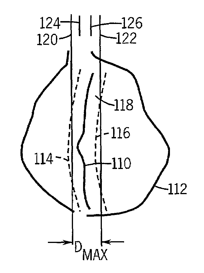
[0010]The invention includes a technique that is a hybrid between multi-phase, single slice and single phase, multi-slice techniques. As applied to MR coronary angiography, the invention includes tracking coronary artery movement during a cardiac cycle as the coronary artery moves between two excursion positions in the R—R interval. The technique includes determining a function of the coronary artery movement having at least a non-linear component that represents movement during a diastolic portion of the R—R interval. Slice position acquisition is adjusted using the determined function and MR data is acquired during each such adjustment. The resulting MR images reconstructed have increased imaging efficiency using the MR data acquired.
[0012]Yet another aspect of the invention includes an MRI apparatus to track and image a moving object-of-interest that includes a magnetic resonance imaging system having an RF transceiver system and a plurality of gradient coils positioned about the bore of a magnet to impress a polarizing magnetic field. An RF switch is controlled by a pulse module to transmit RF signals to an RF coil assembly to acquire MR images. A computer is programmed to acquire a series of scout scans of the object-of-interest using a multi-phase, single slice acquisition pulse sequence as the object-of-interest moves from one position to another. A reference position in a scout scan is identified and the movement of the object-of-interest is tracked by isolating the reference positionin each scout scan in the series of scout scans. A set of motion parameters are determined and stored that include non-linear parameters to accurately prospectively track movement of the object-of-interest.
[0013]In accordance with yet another aspect of the invention, a computer program is disclosed having a set of instructions which, when executed by a computer, cause the computer to track coronary artery movement during a cardiac cycle as the coronary artery moves between two positions. The computer is also caused to determine movement parameters of the coronary artery movement that has at least a non-linear component that represents movement during a diastolic portion of a R—R interval, and then stores the movement parameters in memory. Slice position acquisition is then adjusted using the stored movement parameters and image data is acquired during each such adjustment such that an image is reconstructed having increased imaging efficiency.
[0014]The imaging efficiency is defined as the percentage of the slices where more than 30 mm of the vessel is visualized. Since vessel tracking is preferably implemented on a spiral gradient-echo pulse sequence achieving sub-millimeter spatial resolution, as well as a higher signal-to-noise ratio (SNR), a significant improvement in the efficiency of the vessel tracking sequence was achieved. When using a cross-correlation algorithm for vessel tracking, imaging efficiency is increased even further. Additionally, a higher flip angle can be used to obtain improved image quality since the sequence repetition times are higher in the spiral sequence. The software implementing this technique can be integrated into the operator's console to achieve real-time prescription.

Problems solved by technology

Moving objects are particularly difficult to image, especially if an imaging plane is set in space with the object moving in and out of the imaging plane.
Such imaging is especially difficult when a second periodic motion is added thereto.
For example, imaging of objects in a subject which is breathing causes a periodic motion of internal structures, which is also further complicated by the beating motion of the heart if the structure is near the heart.
While such methods require that segments of the coronary artery be constrained within the plane of the prescribed slices, they do not make any implicit assumptions regarding the motion of the coronary arteries over the entire R—R interval.
This implies that visualization of the vessel in its entirety generally requires several repeated breath-holds covering overlapping or contiguous slice locations, prolonging the scan times, which is generally not acceptable for patients with coronary artery disease.
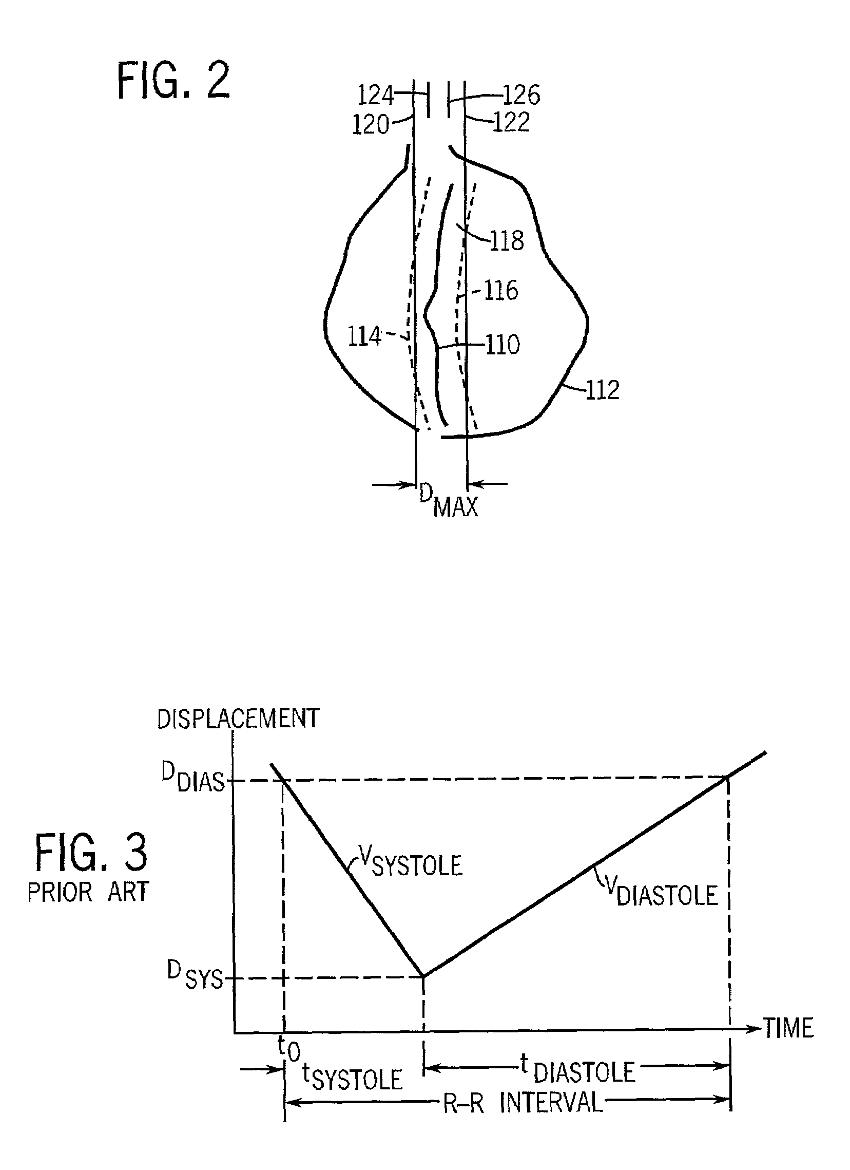
While this linear model is often accurate in systole, during diastole, especially for the RCA, it is not.
It has been found that the motion in diastole does not fit the linear model.
As a consequence, the visualization efficiency in the diastolic phase, where the vessel moves the least, was less than optimal.

Method used


Image

  • Method and apparatus for automated tracking of non-linear vessel movement using MR imaging
  • Method and apparatus for automated tracking of non-linear vessel movement using MR imaging
  • Method and apparatus for automated tracking of non-linear vessel movement using MR imaging

Examples


Embodiment Construction

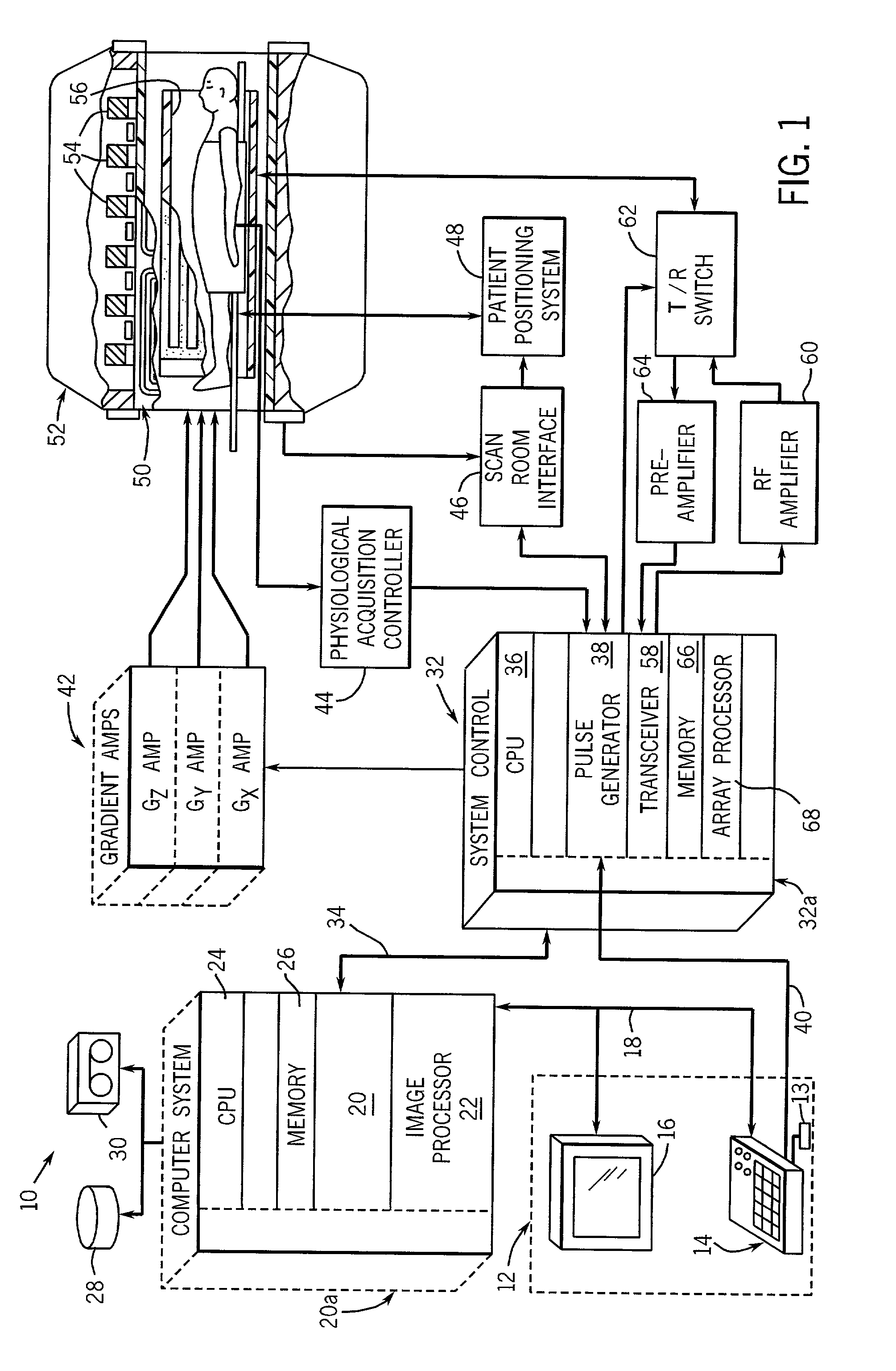
[0024]Referring to FIG. 1, the major components of a preferred MRI system 10 incorporating the present invention are shown. The operation of the system is controlled from an operator console 12 which includes a keyboard or other input device 13, a control panel 14, and a display 16. The console 12 communicates through a link 18 with a separate computer system 20 that enables an operator to control the production and display of images on the screen 16. The computer system 20 includes a number of modules which communicate with each other through a backplane 20a. These include an image processor module 22, a CPU module 24 and a memory module 26, known in the art as a frame buffer for storing image data arrays. The computer system 20 is linked to a disk storage 28 and a tape drive 30 for storage of image data and programs, and it communicates with a separate system control 32 through a high speed serial link 34. The input device 13 can include a mouse, joystick, keyboard, track ball, to...


PUM


Abstract

A system and method is disclosed for tracking a moving object using magnetic resonance imaging. The technique includes acquiring a scout image scan having a number of image frames and extracting non-linear motion parameters from the number of image frames of the scout image scan. The technique includes prospectively shifting slice location using the non-linear motion parameters between slice locations while acquiring a series of MR images. The system and method are particularly useful in tracking coronary artery movement during the cardiac cycle to acquire the non-linear components of coronary artery movement during a diastolic portion of the R—R interval.

Description

BACKGROUND OF THE INVENTION[0001]The present invention relates generally to an improved method for acquiring magnetic resonance images (MRI) of moving objects, and more particularly to, a method and apparatus to improve the efficiency of magnetic resonance coronary angiography (MRCA).[0002]When a substance such as human tissue is subjected to a uniform magnetic field (polarizing field B0), the individual magnetic moments of the spins in the tissue attempt to align with this polarizing field, but precess about it in random order at their characteristic Larmor frequency. If the substance, or tissue, is subjected to a magnetic field (excitation field B1) which is in the x-y plane and which is near the Larmor frequency, the net aligned moment, or “longitudinal magnetization”, MZ, may be rotated, or “tipped”, into the x-y plane to produce a net transverse magnetic moment Mt. A signal is emitted by the excited spins after the excitation signal B1 is terminated and this signal may be recei...

Claims


Application Information

Patent Timeline
IPC IPC(8): A61B5/05A61B5/055G01R33/56G01R33/567
CPCA61B5/055G01R33/56509A61B5/7285G01R33/5673G01R33/56A61B5/0037
Inventor SARANATHAN, MANOJKUMARHARDY, CHRISTOPHER J.FOO, THOMAS K. F.
Owner GENERAL ELECTRIC CO
Learn More