
Crystallization apparatus using pulsed laser beam

a laser beam and crystallization technology, applied in metal working apparatus, manufacturing tools, instruments, etc., can solve the problems of reducing the fair quality ratio (the yield ratio) of the final product, machining defects, and insufficient crystallization or activation, etc., to achieve excellent laser crystallization performance, reduce the yield ratio, and process accurately without defects

Inactive Publication Date: 2007-07-24
ADVANCED LCD TECH DEVMENT CENT
View PDF9 Cites 12 Cited by
  • Summary
  • Abstract
  • Description
  • Claims
  • Application Information

AI Technical Summary

Benefits of technology

[0024]According to the above-described method, the conventional drawbacks are eliminated, and it is possible to provide a processing target body having, e.g., an excellent yield ratio.
[0051]Furthermore, according to the present invention, it is possible to excellently perform laser crystallization without lowering a yield ratio since an abnormal shot is detected to thereafter perform repairing even if the abnormal shot occurs in application of a laser beam for crystallization.

Problems solved by technology

If there is a failure of laser oscillation in one execution of laser irradiation due to any factor, there occurs a problem of a machining defect if nothing is fed back to a laser device.
Specifically, when laser irradiation is not carried out or a light intensity of laser irradiation is lower than a set value, a region which is not machined well is generated, resulting in a reduction in a fair quality ratio (a yield ratio) of a final product.
Further, in crystallization based on laser annealing for other pulsed laser processing applications, if there is a part which has not been irradiated with a laser beam or a part in which an irradiation light intensity of a laser beam has not been enough, this part is not crystallized at all, or crystallization or activation becomes insufficient.
Therefore, intended uniformity of characteristics or electrical characteristics cannot be obtained, which is a serious problem.
Furthermore, in a case where a laser processing method is used in a field using a laser processing method except the semiconductor field, e.g., machining of an ink discharge hole part of an inkjet head in an inkjet printer, if a laser beam is not applied to a given part or an irradiation light intensity of a laser beam is insufficient, a hole is not opened or hole machining becomes insufficient, and a yield ratio is likewise reduced in this field, resulting in a serious problem.
However, the excimer laser has instability in oscillation characteristics.
Although an excimer laser which does not use thyratron has been developed, a large load is imposed on a power supply circuit, thereby reducing reliability or increasing a cost.
This problem is realized as great irregularities of a machining conformation in a machining process, which is interference of mass production.
In the processing method in the above-described reference, however, there are the following two problems.
That is, firstly, since a position at which a laser beam intensity is monitored is not a processing target material surface, there is a problem that an accurate laser beam intensity on the processing target material surface cannot be grasped.
Secondly, moving an X-Y stage to return to an abnormal processing point and again applying a laser beam has no problem in case of rough processing of several-ten μm, but there is a limit in a mechanical accuracy in microfabrication which requires a positional accuracy of a processing point which is approximately 0.1 to 1.0 μm, and hence there is a problem that uniform processing is impossible (this problem can be solved by improving the mechanical accuracy).
Next, in case of forming a liquid crystal drive circuit which forms a large display screen of a liquid crystal display device in a crystallized region, there are the following problems.
In a process of sequentially moving a pulsed laser beam to a predetermined irradiation position in a large display screen to thereafter apply the pulsed laser beam, when any problem exists in laser irradiation of one given shot (an abnormal shot), a serious problem occurs in crystallization of the irradiation position.
For example, when laser irradiation is not performed or when a light intensity of laser irradiation is low, crystallization does not occur, or crystallization becomes insufficient.
Further, besides the laser crystallization process, in activation of a semiconductor implanted layer based on laser annealing, when a laser beam is not applied or when an irradiation light intensity of a laser beam is low, this part is not activated at all, or activation becomes insufficient.
Therefore, intended electrical characteristics cannot be obtained, which is a serious problem in quality management.

Method used


Image

  • Crystallization apparatus using pulsed laser beam
  • Crystallization apparatus using pulsed laser beam
  • Crystallization apparatus using pulsed laser beam

Examples


first embodiment

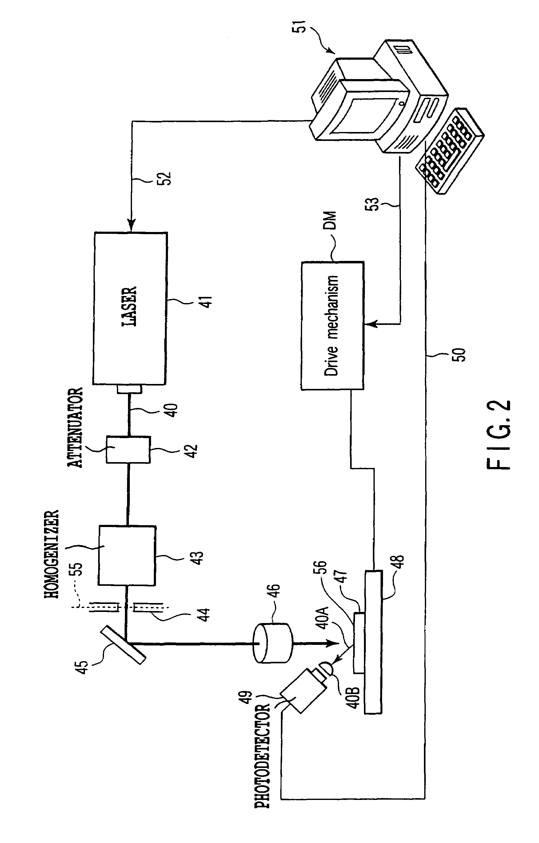
[0085]A laser processing apparatus using a pulsed laser beam and a laser processing method using a pulsed laser beam will now be described with reference to FIG. 2. FIG. 2 is a system block diagram showing a laser processing apparatus using a pulsed laser beam. In these examples, an excimer laser beam source 41 (e.g., XeCl, KrF, ArF or the like) having a large output is used as a pulsed laser beam source, but the present invention is not restricted thereto, and a solid laser such as a third harmonic wave or fourth harmonic wave of Q switched YAG laser may be used.

[0086]As shown in FIG. 2, an attenuator 42 which controls a light intensity of a pulsed laser beam 40 and a homogenizing optical system 43 which homogenizes an intensity of a laser beam on a two-dimensional plane are sequentially arranged in an exit optical path of the excimer laser beam source 41 which emits the pulsed laser beam 40.

[0087]It is to be noted that a position denoted by reference numeral 55 corresponds to a pr...

second embodiment

[0130]A second embodiment is an example in which a processed state of a processing target body 47 is optically observed and a desired processed state and an unprocessed state are judged. FIG. 9 is a system block diagram illustrating an embodiment of an ablation apparatus which optically observes and evaluates a processed state (a result) of the processing target body 47. Like reference numerals denote parts equal to those in FIGS. 1 to 8, and their detailed explanation will be eliminated.

[0131]As shown in FIG. 9, the second embodiment is an example where a part of the processing target body 47 processed by a pulsed laser beam 40 from a laser beam source 41 is illuminated by additionally prepared optical observing means so that a processed result is observed. A probe light source 54 may be a lamp or a semiconductor laser which performs continuous oscillation. The processed position is irradiated with a laser beam emitted from this probe light source 54.

[0132]A photodetector 49 is arr...

third embodiment

[0135]As shown in FIG. 10, a third embodiment is an example in which a laser beam source 41 and a second laser beam source 404 are prepared and a processed position of a processing target body 47 is illuminated by additionally prepared optical observing means to observe each processing result each time. A pulsed laser beam 401 emitted from the laser beam source 41 is combined with a pulsed laser beam 402 emitted from the laser beam source 404 by a half mirror 403, and the laser beam emitted from each laser beam source becomes a pulsed laser beam 40 after transmitted through the half mirror 403. Usually, one of the laser beam source 41 and the laser beam source 404 is used to perform processing.

[0136]A photodetector 49 detects evaluation information of a processed state of the processed position, and quality of processing is grasped and determined based on a fact whether a signal value monitored by the photodetector 49 is a value obtained when normal processing has been carried out (...


PUM


Abstract

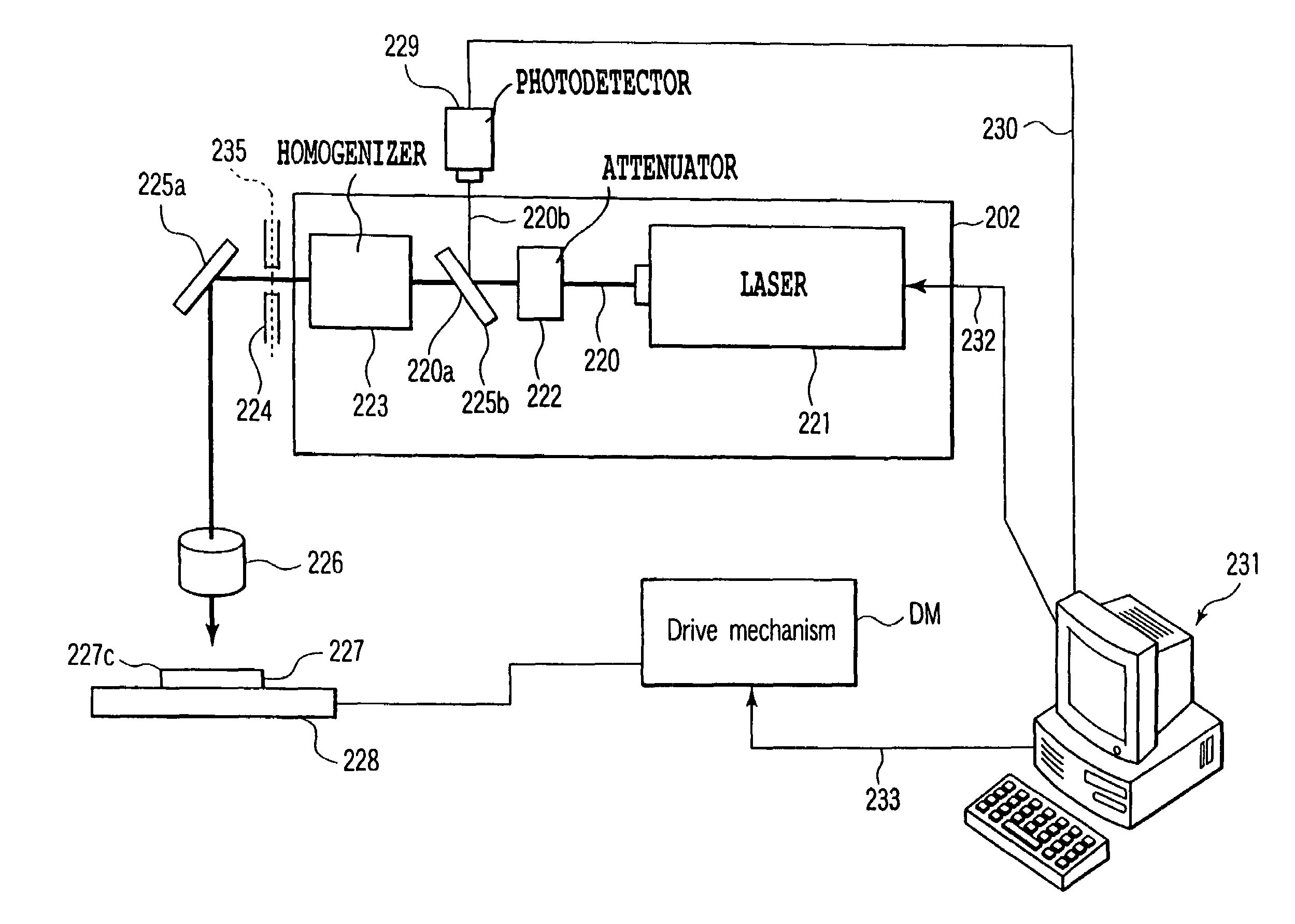
In a laser processing method and a laser processing apparatus which irradiate a processing target body with a laser beam pulse-oscillated from a laser beam source, a processing state is monitored by a photodetector, and the laser beam source is again subjected to oscillation control on the moment when erroneous laser irradiation is detected, thereby performing laser processing. Further, in a laser crystallization method and a laser crystallization apparatus using a pulseoscillated excimer laser, a homogenizing optical system, an optical element and a half mirror are arranged in an optical path, light from the half mirror is detected by a photodetector, and a light intensity insufficient irradiation position is again irradiated with a laser beam to perform crystallization when the detection value does not fall within a range of a predetermined specified value.

Description

CROSS-REFERENCE TO RELATED APPLICATIONS[0001]This application is based upon and claims the benefit of priority from prior Japanese Patent Applications No. 2004-299222, filed Oct. 13, 2004; and No. 2005-275866, filed Sep. 22, 2005, the entire contents of both of which are incorporated herein by reference.BACKGROUND OF THE INVENTION[0002]1. Field of the Invention[0003]The present invention relates to a processing method using a pulsed laser beam, a processing apparatus using a pulsed laser beam which carries out this method, crystallization method using a pulsed laser beam, a laser crystallization apparatus which carries out this method, and a display device.[0004]2. Description of the Related Art[0005]A machining technology using an excimer laser which is a pulsed laser beam has been extensively studied and developed for process applications such ablation (evaporation), heating or melting. In recent years, an ablation technology has been extensively reviewed with respect to soft orga...

Claims


Application Information

Patent Timeline
Patent Type & Authority Patents(United States)
IPC IPC(8): B23K26/00H01L21/268
CPCB23K26/03B23K26/032B23K26/063B23K26/0853B23K2201/40B23K26/0622B23K2101/40
Inventor JYUMONJI, MASAYUKIOGAWA, HIROYUKIHIRAMATSU, MASATOAKITA, NORITAKAKATO, TOMOYA
Owner ADVANCED LCD TECH DEVMENT CENT
Learn More