

Surface graft material, conductive pattern material, and production method thereof
a technology of surface graft and conductive pattern, which is applied in the direction of photosensitive materials, liquid/solution decomposition chemical coatings, instruments, etc., can solve the problems of troublesome process and large problem of remaining by-product homopolymers, and achieve high sensitivity and high durability
- Summary
- Abstract
- Description
- Claims
- Application Information
AI Technical Summary
Benefits of technology
Problems solved by technology
Method used
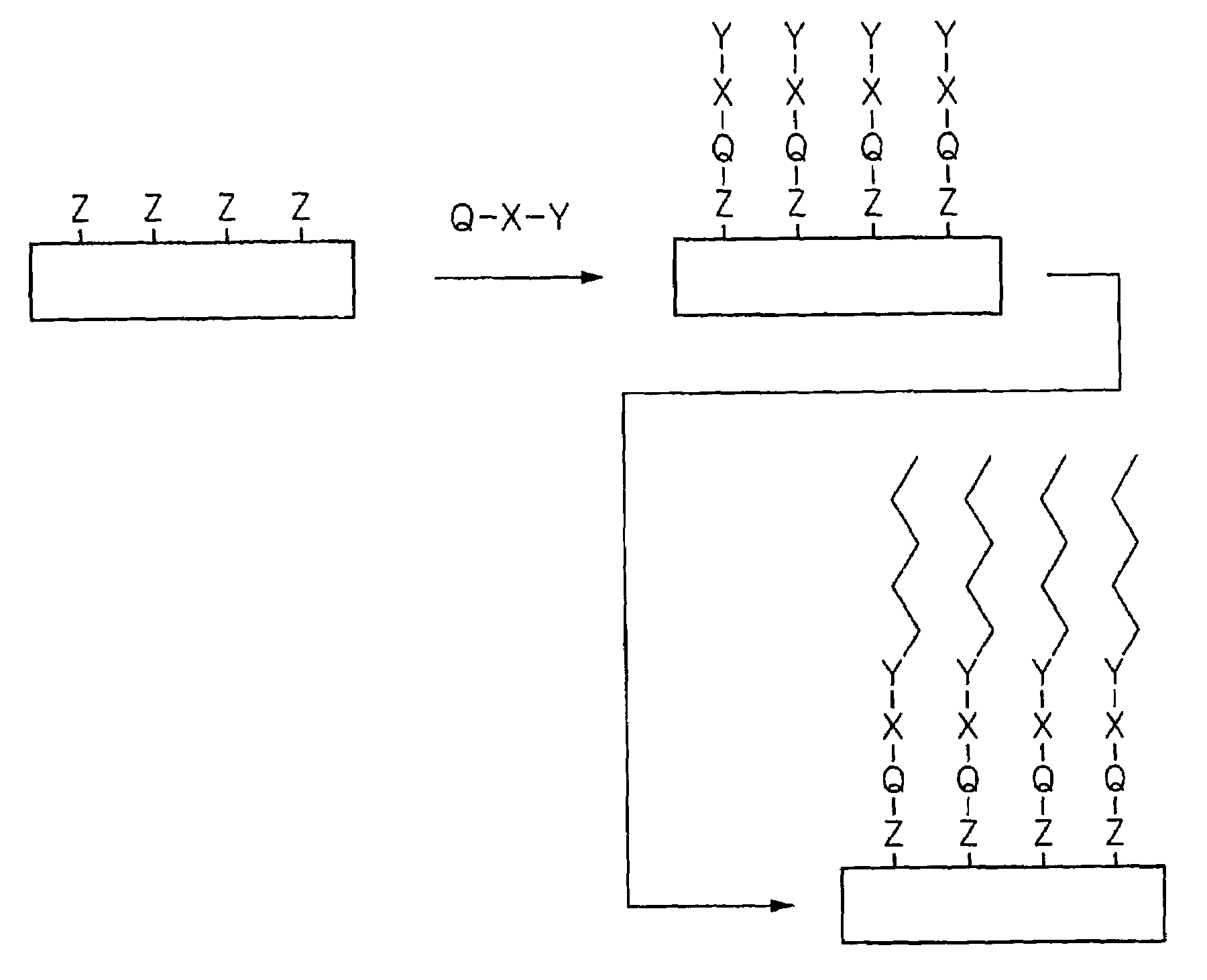
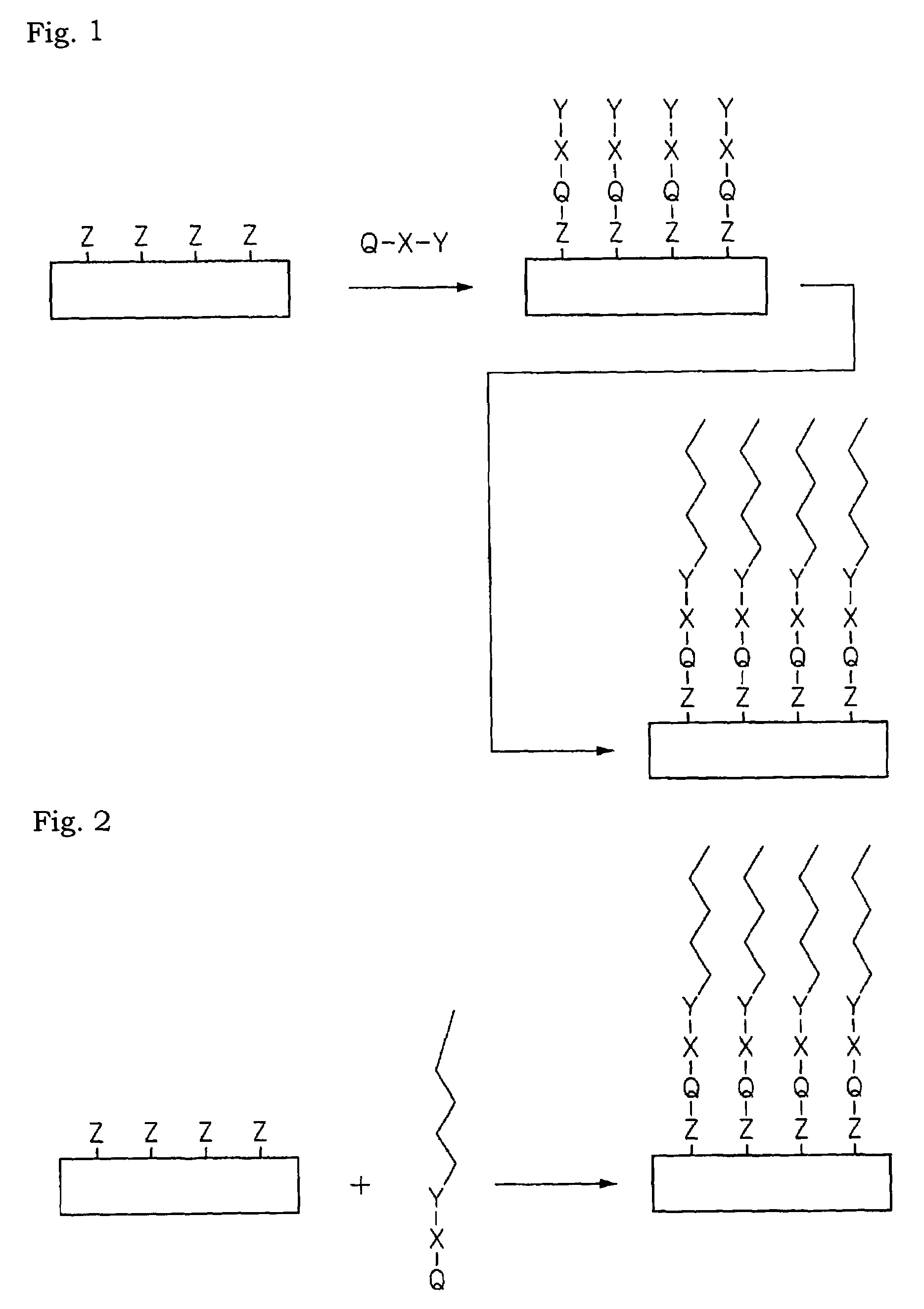
Image

Examples
synthesis example 1
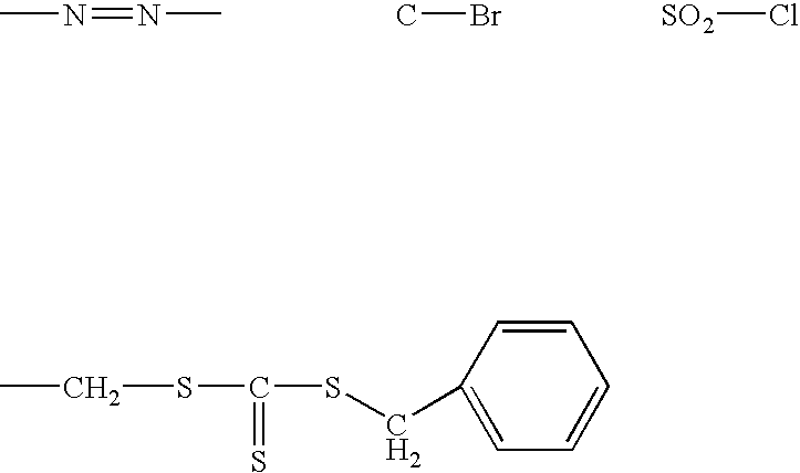
Synthesis of Photocleavable Silane-Coupling Compound 1
[0165]The synthesis of the exemplary compound 1 shown above as an example of the compound (Q-X-Y) is conducted through the following four steps. Schemes of the respective steps will be explained.
1. Synthesis of ATRP Initiator [1] (Introduction of Olefin by an Etherization (Williamson Reaction))
[0166]Into a nitrogen-substituted 1000 ml three-neck flask, 22.4 g (0.1 mol) of 4-hydroxy-4′-hydroxyethoxy)-2-methylpropiophenone and 300 g of tetrahydrofuran (THF) were poured followed by cooling with an ice bath under stirring. Thereto, 9.7 g (0.24 mol) of NaH (60 to 72% in oil) was gradually added and the ice bath was removed at the completion of the addition, and the liquid was stirred for 2 hrs. The liquid was cooled again with the ice bath, and a half of a solution obtained by dissolving 13.3 g (0.11 mol) of allyl bromide in a mixture of 25 g of THF and 25 g of dimethyl acetamide (DMAc) was gradually dropped. The remaining half was dr...
example 1
(Preparation of Graft Substrate A-1 (Acrylic Acid Graft))
[0181]A silicon substrate was washed with Piranha solution ((30% by weight) H2SO4 / H2O2=1 / 1 (v / v) mixture). Then, the substrate was immersed in a 1% by mass dehydrated toluene solution of a silane coupling agent having an initiator (the exemplary compound 1 obtained in the synthesis example 1) under argon atmosphere overnight to fix the initiator onto the silicon substrate. Then, the substrate with the initiator was placed in a separable flask, immersed under argon current in an aqueous solution of sodium acrylate including copper chloride (I) and 2, 2′-bipyridyl as catalysts, then the solution was stirred, then the flask was left overnight. In this way, a graft substrate A-1 was obtained. The film thickness was measured by elipsometry and found to be 100 nm.
(Preparation of Graft Pattern A-1 (Acrylic Acid Graft Pattern))
[0182]The graft silicon substrate A-1 was brought into close contact with a mask pattern (trade mark: NC-1 ma...
example 2
(Preparation of Graft Substrate A-2 (Methyl Methacrylate)
[0184]An initiator was fixed onto a silicon substrate in the same manner as the preparation of the graft substrate A-1 in the example 1. Then, the substrate having the initiator was placed in a separable flask. Diphenyl ether containing copper bromide (I) (0.01 M) and 4,4′-dis-neptyl-2,2′-bipyridine (0.02 mol), p-toluenesulfonyl chloride (0.0024 mol) and MMA (methyl methacrylate, 4.7M) were added into the flask. In the flask, the substrate was immersed in the above liquid and allowed to react at 90° C. for 10 hrs. Thereafter, the substrate was taken out and thoroughly washed with chloroform. The film thickness was measured by elipsometry and found to be 80 nm.
(Preparation of Pattern A-2 (Methyl Methacrylate Graft Pattern))
[0185]The graft silicon substrate A-2 was brought into close contact with a mask pattern (trade mark: NC-1 manufactured by Toppan Printing Co., Ltd.) formed on a quartz plate, and irradiated with a UV light f...
PUM
| Property | Measurement | Unit |
|---|---|---|
| particle size | aaaaa | aaaaa |
| temperature | aaaaa | aaaaa |
| diameter | aaaaa | aaaaa |
Abstract
Description
Claims
Application Information