Coated power cylinder components for diesel engines

a technology for power cylinders and components, applied in machines/engines, trunk pistons, plungers, etc., can solve the problems of piston erosion, piston rot, and subsequent lubricant oil control loss, so as to reduce the deleterious effect, reduce the cost of lubricant oil control, and increase the life of intricate stamping dies.

Active Publication Date: 2008-06-10
FEDERAL MOGUL WORLD WIDE LLC
View PDF32 Cites 12 Cited by
  • Summary
  • Abstract
  • Description
  • Claims
  • Application Information

AI Technical Summary

Benefits of technology

[0011]The inventor has found that an electroplate coating typically used in the stamping industry, and sometimes used in the auto racing field to coat the skirts of gasoline engine pistons which do not suffer from the problems described above in connection with high pressure diesel engines with EGR, is highly effective in overcoming or greatly minimizing the deleterious effects that the diesel engine environment has on steel pistons as described above. “DIA-CLUST” is a trademark of a product used by some electroplating job shops in the United States. The process was developed to increase the life of intricate stamping dies. It consists of electroplating in-place a mixed layer of chromium and industrial diamonds. The diamond clusters are extremely small (less than 40 nm) in size. The electroplated layer exhibits a very smooth surface and a very low coefficient of friction (about 0.08). The coating for diesel engine applications is on the order of about 2 to 10 μm.
[0012]The chromium in the layer imparts corrosion and oxidation resistance to the power cylinder components coated with the composite chromium / diamond coating and is responsible for reduced groove wear / pin bore triboligical behavior and top land carbon build up avoidance. The combined effects of the Cr and diamond clusters also impart resistance to scuffing of the skirt portions of the piston and cavitation of the liner, thus enabling pistons to run at much tighter running clearances, when applied to piston skirts without concern for localized welding or seizing of the piston within the liner. Mitigating liner cavitation is tantamount to reducing assembly clearances afforded by the lubricious nature of the coating.

Problems solved by technology

Also, due to late fuel injection timing necessary to preclude NOx formation, instances of liner fuel overspray have been documented.
There are several side effects to these conditions inherent with high pressure diesel injections systems, including: 1) the build-up of carbon deposits on the top land of diesel engine pistons, 2) the deterioration of the oil film at top dead center / top ring reversal point on the liner and 3) piston erosion (pitting) particularly where the plumes from the injectors fire on the top bowl edge of the piston.
Top land carbon build up is historically singled out as the root cause of bore polishing and subsequent lubricant oil control loss.
Emissions are then adversely affected.
Liner overspray with fuel dilutes and contaminates the oil film, greatly affecting the ability of the squeeze film to handle the first ring contact load.
Chemical etching (corrosion) of the liner on the first 20 to 40 mm of the piston travel from TDC not only leads to accelerated local wear, but also leads to higher ring peripheral (OD) face wear.
Local uncontrolled (explosive) deposited fuel burn creates extremely high thermal and mechanical stressing of the piston material.
Eventually pitting occurs and will structurally weaken reentrant combustion bowl overhang lip and breakage can occur.
Emissions and overall engine performance are adversely affected.
What has been described thus far are typical problems, to a greater or lesser degree, derived from in-cylinder environment created by emissionized engines having EGR.
In addition, the high rate of pressure rise and high peak combustion pressure characteristic of modern diesel engines slap the piston against and excite the liner's vibratory motions, triggering liner cavitation which can be a major problem itself.
Skirt coatings (polymer based or graphite impregnated) are expected to help diminish cavitation but they bring additional problems of their own, besides being cumbersome to apply during manufacture.

Method used


Image

  • Coated power cylinder components for diesel engines
  • Coated power cylinder components for diesel engines
  • Coated power cylinder components for diesel engines

Examples


Embodiment Construction

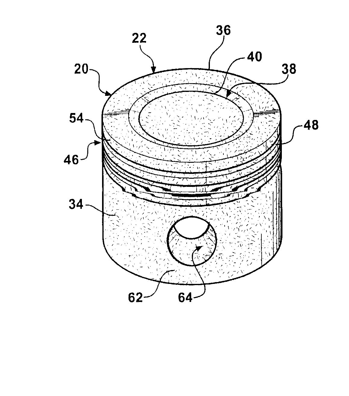
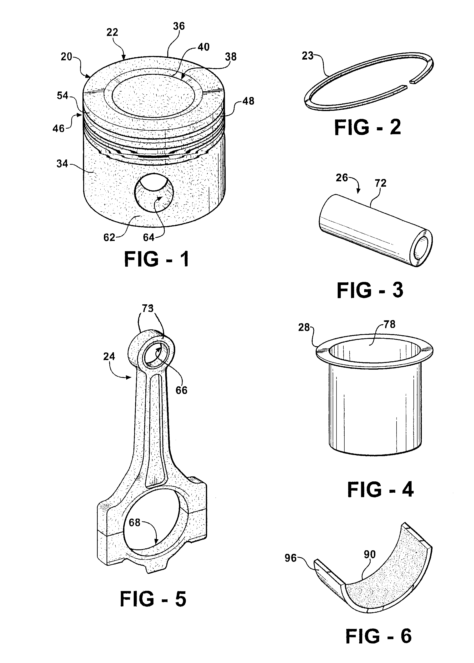
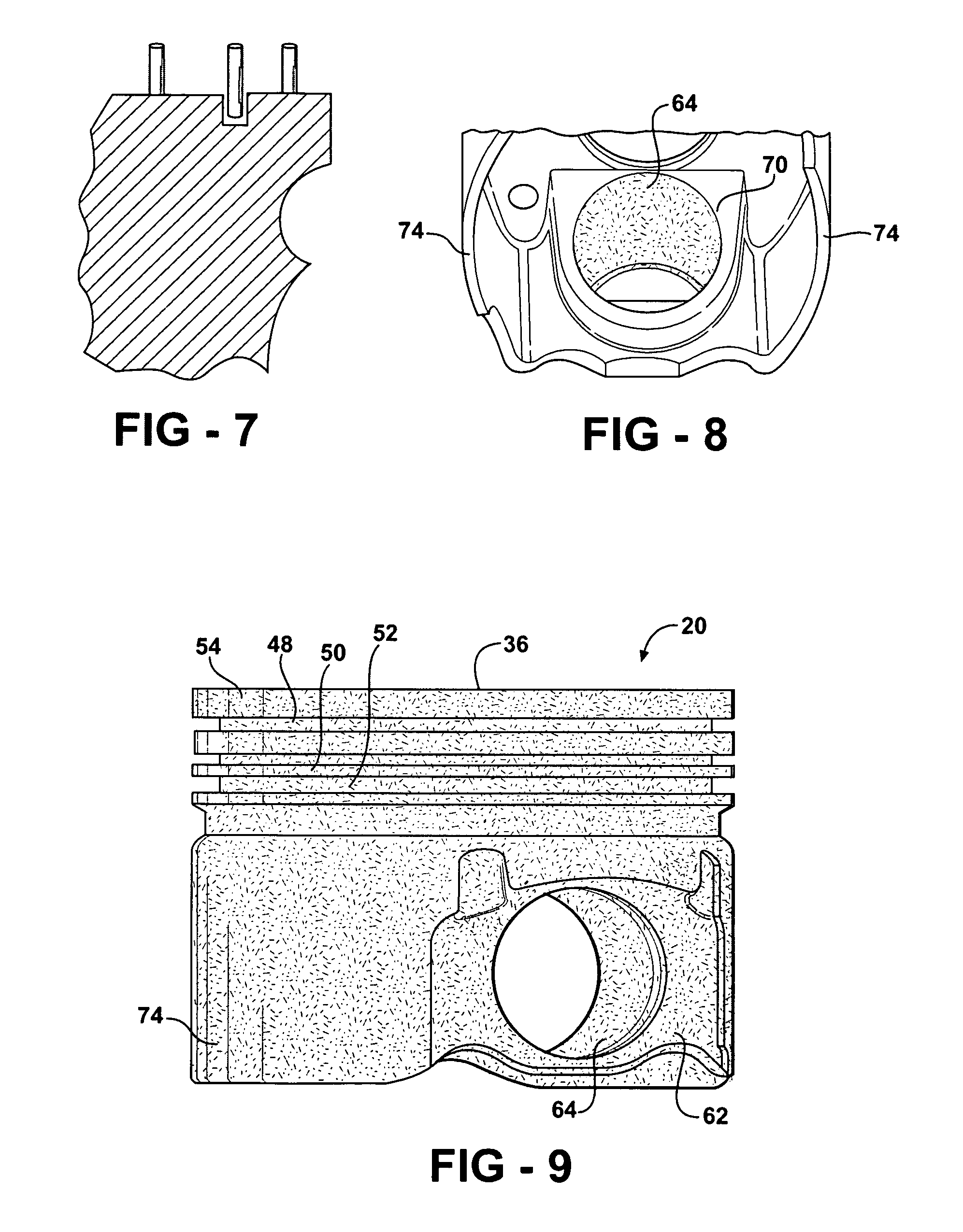
[0027]FIGS. 1 and 8-10 illustrate a piston 20 of a piston assembly 22 which includes the piston 20, one or more piston rings 23, a connecting rod 24 and a wrist pin 26. The piston assembly 22 is part of a power cylinder assembly 27 which additionally includes a cylinder liner 28, a crankshaft 30 and an engine block 32. Those skilled in the art of diesel engines will understand how these components connect to one another and operate and thus a detailed description is not necessary, with the schematic views being sufficient for an understanding of the working of the components in the context of the invention.

[0028]The piston 20 includes a piston body 34. For many diesel applications, a piston fabricated of steel is preferable, although other materials are contemplated such as iron and aluminum.

[0029]The piston body 34 has a top surface 36 in which a combustion bowl 38 is recessed. The bowl 38 may be shaped to include a bowl rim or lip 40 which, as illustrated, may project radially inw...


PUM


Abstract

A diesel engine piston assembly comprises a piston body having a top wall with a combustion bowl formed in the top wall and having a combustion bowl edge, an outer ring belt formed with a plurality of ring grooves including a top ring groove with an upper wall of the top ring groove and a top land portion of the ring belt disposed between the top ring groove and the top wall, a pair of pin bosses with aligned pin bores and a skirt; and a diamond dispersed chromium composite coating applied to at least the top wall, the combustion bowl edge, the top land portion and the upper wall of the top ring groove.

Description

[0001]This application claims priority to and incorporates by reference U.S. Provisional Application 60 / 683,575 filed May 23, 2005.BACKGROUND OF THE INVENTION[0002]1. Technical Field[0003]This invention relates generally to diesel engines and more particularly to coatings used to protect the various power cylinder components of the power cylinder including the piston.[0004]2. Related Art[0005]Many ways and means exist to protect in-cylinder diesel engine components from deleterious effects of combustion by-products, notably when EGR (exhaust gas recirculation) is used in the engine. Also, it has been proposed to use coatings as joint tribological elements in lieu of bushings and bearings and the like. As examples of the latter, manganese phosphate, DLC (diamond-like-coatings), many variations of PVD (physical vapor deposition)-derived coatings, electroless and electroplated layers.[0006]With widespread use of high pressure diesel engine injection systems (common rail, electronic uni...

Claims


Application Information

Patent Timeline
Patent Type & Authority Patents(United States)
IPC IPC(8): F02F3/00
CPCF02F3/0084F16J1/04F16J1/02F02F3/14F02F3/02F02F3/10
Inventor AZEVEDO, MIGUELAINSWORTH, GEOFFREY N.
Owner FEDERAL MOGUL WORLD WIDE LLC
Why Eureka
Try Eureka