
Flexible network wireless transceiver and flexible network telemetry transceiver

a flexible network and wireless transceiver technology, applied in the field of flexible network wireless transceiver and flexible network telemetry transceiver, can solve the problems of affecting the overall communication and information exchange, affecting the interoperability of the global network, and several smart and dumb munitions and missiles used by the armed forces are not integrated into the global grid. , to achieve the effect of improving jamming margin, high data rate and robust performan

Inactive Publication Date: 2008-08-05
THE UNITED STATES AS REPRESENTED BY THE DEPARTMENT OF ENERGY
View PDF9 Cites 94 Cited by
  • Summary
  • Abstract
  • Description
  • Claims
  • Application Information

AI Technical Summary

Benefits of technology

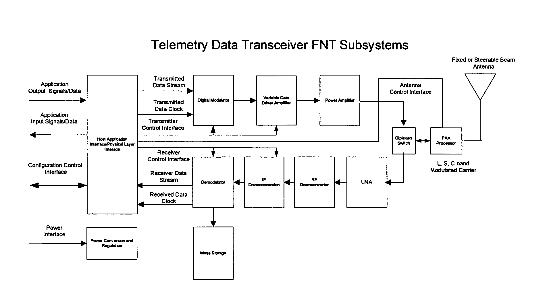
[0013]The flexible telemetry receiver (FTR) is a compact, lightweight, modular, portable, ruggedized, data communication RF / microwave receiver that provides an RF receive channel for the wireless network channel to the communication processor, and converts the received RF signals to baseband digital signals for use by the baseband waveform processor. The FTR amplifies weak RF signals, extracts data from the received carrier, and converts it to a number of standard waveforms such as JTRS waveforms which can be demodulated into a serial data stream with a corresponding synchronous clock. Each are distinct in function (voice, video, data), bandwidth (data rate), and modulation. It also functions to digitize and store a time record of the output IF signal for post-experimental laboratory analysis. The FTR can be adapted in real-time through several degrees of freedom in order to dynamically reconfigure for changing data rates, modulation type, selectivity, IF gain and bandwidth, IF frequency, sample rate, video bandwidth, and video, and to configure RF gain and manage noise performance. Furthermore, the FTR's design is scalable because it is modular with standard interfaces to facilitate logical substitution of RF, IF, and baseband segments in order the enable flexibility across a broad range of frequency and link margin applications (L, S, C, and X frequency bands, link margins, FH / DSSS, OFDM waveforms, multiple access, bandwidth, data rates). The FTR architecture is modular and incorporates standard interfaces, so it is capable of scaling to other frequency bands and other power levels to support a broad range of applications. The FTR includes a low noise amplifier (LNA); a frequency downconverter; a real-time demodulator; and a mass storage unit. The LNA amplifies very weak signals while minimizing the impact of noise, thereby producing sufficient signal-to-noise ratios at the frequency downconverter so that the modulating signal can be extracted in the demodulator. The frequency downconverter translates the S or L band microwave signal down to a standard first intermediate frequency (IF), where a range of adjacent second IF chains can be driven from a common IF frequency. The demodulator serves as a configurable baseband waveform processor which digitizes IF signals and filters and processes them within a CPLD digital signal processor such that BPSK, GFSK, GMSK, QPSK, or SOQPSK and eventually multi-h CPM modulated PCM data can be produced as a serial stream on the output. The mass storage unit digitizes the IF signals from the frequency downconverter and stores these samples internally for post-application laboratory digital signal analysis. The mass storage unit will provide standard (USB) interface for downloading of digitized IF data streams.
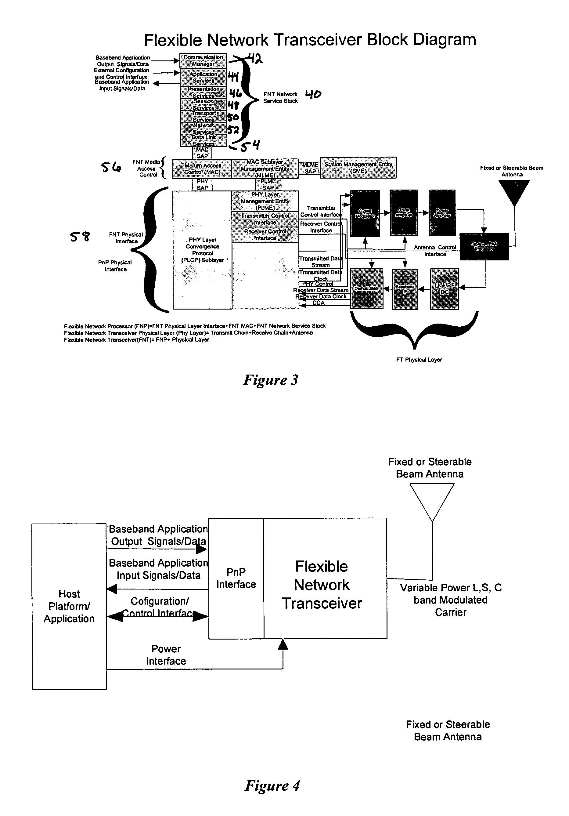
[0040]When a plug and play (PnP) interface is added to the FNT such that the FNT is compatible with a standard interface bus such as USB or Firewire, then the rapid embedding of the FNT can be accomplished. This enables very responsive communication links on a host of mobile platforms.

Problems solved by technology

Unfortunately certain classes of mobile and fixed platforms are not currently integrated into this global grid, leaving a glaring gap or hole in the overall communication and information exchange and undermining global connectivity and interoperability among the various interested information consumers.
Unfortunately, several smart and dumb munitions and missiles used by the Armed Forces are not integrated into the global grid.
As a result, command and control, intelligence, surveillance, reconnaissance, and weapon delivery platforms suffer from fragmented perspectives, stratified “kill-chain” processes, “stove-piped” infrastructure, poor interoperability and interconnectivity, limited infrastructure availability, limited data availability, and limited scope.
Current commercial off the shelf (COTS) products do have limitations.
For example, COTS 802.11 network hardware presents such issues as eavesdropping, security, intrusion, interference, range, fixed quality of service, latency, throughput, power efficiency, limited bandwidth, number of users, message prioritization, multiple access, fading RF channels, coverage area, environmental sensitivity, fixed modulation, etc.
However, the ever increasing demands posed by the applications are stretching the 802.11 protocol beyond its intended capabilities.
For example, 802.11 provides for no control over allocation of resources, and the default allocation policy is ill suited for multi-hop networks.
Furthermore, senders with heterogeneous data rates can affect the system throughput adversely.
However, this fairness criterion can lead to low throughput when nodes transmit at widely different rates.
This unfairness or bandwidth sharing presents itself as a significant quality of service problem for 802.11 networks.
In addition, the 802.11 has latency problems when using the combination of voice, data and isochronous data packets at data rates of 1 and 11 Mbps.
These factors along with the processing for handling security and encryption have negative impacts upon latency.
This becomes a significant problem when targeting moving objects.

Method used


Image

  • Flexible network wireless transceiver and flexible network telemetry transceiver
  • Flexible network wireless transceiver and flexible network telemetry transceiver
  • Flexible network wireless transceiver and flexible network telemetry transceiver

Examples


Embodiment Construction

, below.

BRIEF DESCRIPTION OF THE DRAWINGS

[0042]A preferred embodiment of the present invention is described in detail below with reference to the attached drawing figures, wherein:

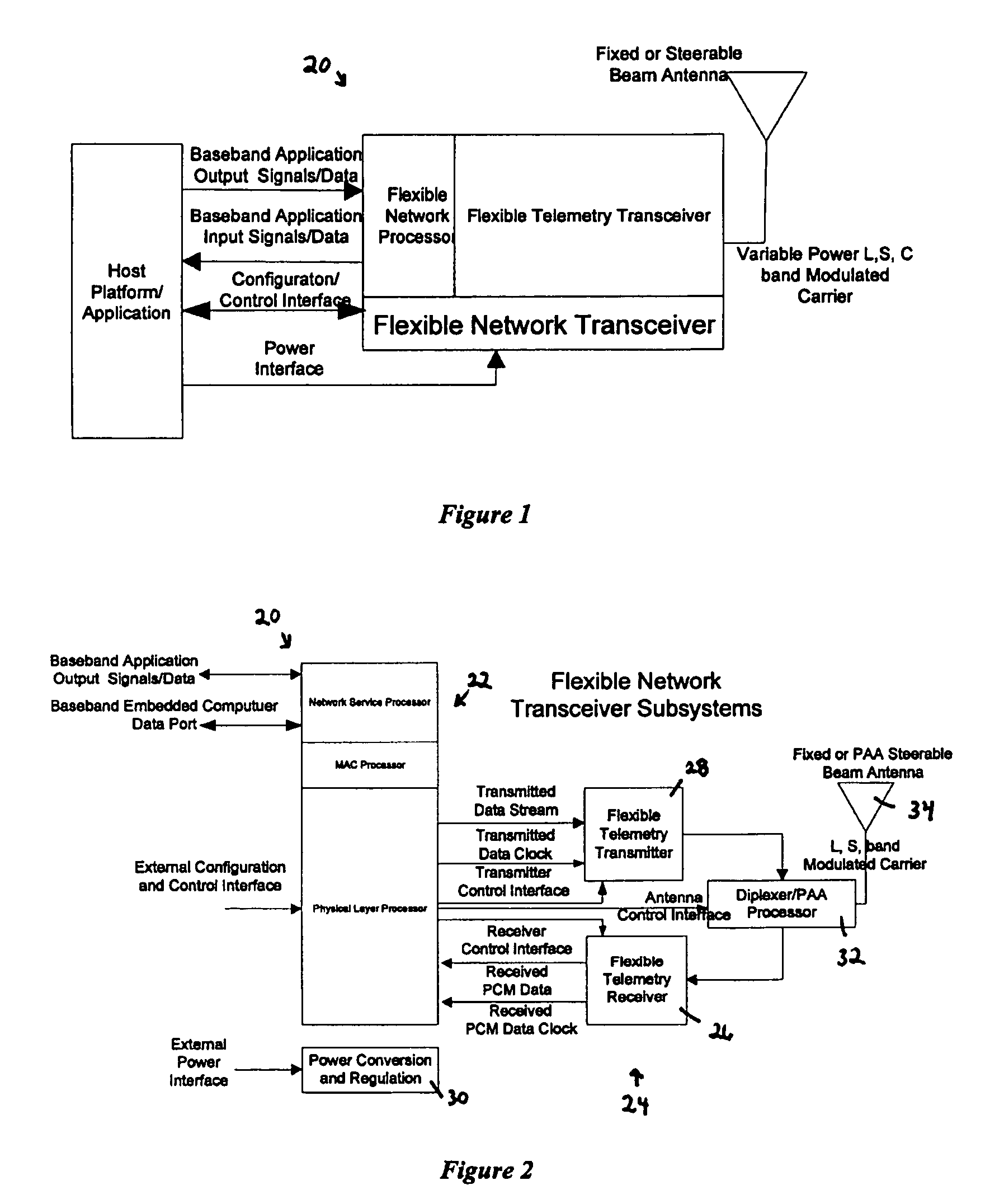
[0043]FIG. 1. Flexible Telemetry Network Application Specific FNT Architecture. The FNT functions to provide communication services between distributed mobile host applications, it provides wireless transmit, receive, antenna, and signal processing to translate baseband data and control signaling that it can propagate across the wireless channel. The host application interface support transfer of synchronization, data, and control signals. The wireless channel interface support transfer of TEM waves to and from the wireless channel.

[0044]FIG. 2. Flexible Network Transceiver (FNT) Subsystem Architecture. Major FNT subsystems include the network processor, distributed transmitter, flexible telemetry receiver, and the phased array antenna. The major interfaces between these functions are also shown.

[0045]FIG....


PUM


Abstract

A transceiver for facilitating two-way wireless communication between a baseband application and other nodes in a wireless network, wherein the transceiver provides baseband communication networking and necessary configuration and control functions along with transmitter, receiver, and antenna functions to enable the wireless communication. More specifically, the transceiver provides a long-range wireless duplex communication node or channel between the baseband application, which is associated with a mobile or fixed space, air, water, or ground vehicle or other platform, and other nodes in the wireless network or grid. The transceiver broadly comprises a communication processor; a flexible telemetry transceiver including a receiver and a transmitter; a power conversion and regulation mechanism; a diplexer; and a phased array antenna system, wherein these various components and certain subcomponents thereof may be separately enclosed and distributable relative to the other components and subcomponents.

Description

CROSS REFERENCE TO RELATED APPLICATIONS[0001]This application claims benefit of U.S. Provisional Application No. 60 / 639,229 filed Dec. 20, 2004.FEDERALLY SPONSORED RESEARCH OR DEVELOPMENT PROGRAM[0002]The present invention was developed with support from the U.S. government under Contract No. DE-AC04-01AL66850 with the U.S. Department of Energy. Accordingly, the U.S. government has certain rights in the present invention.BACKGROUND OF THE INVENTION[0003]1. Field of the Invention[0004]The present invention relates broadly to systems and methods for providing communication between a vehicle or other platform and interested information consumers. More particularly, the present invention concerns a transceiver for facilitating two-way wireless communication between a baseband application, which is associated with a mobile or fixed space, air, water, or ground vehicle or other platform, and other nodes in a wireless network, wherein the transceiver provides baseband communication network...

Claims


Application Information

Patent Timeline
Patent Type & Authority Patents(United States)
IPC IPC(8): H04Q7/00
CPCH04B7/18515
Inventor BROWN, KENNETH D.
Owner THE UNITED STATES AS REPRESENTED BY THE DEPARTMENT OF ENERGY
Learn More