Cryogenic variable temperature vacuum scanning tunneling microscope
- Summary
- Abstract
- Description
- Claims
- Application Information
AI Technical Summary
Benefits of technology
Problems solved by technology
Method used
Image
Examples
example 1
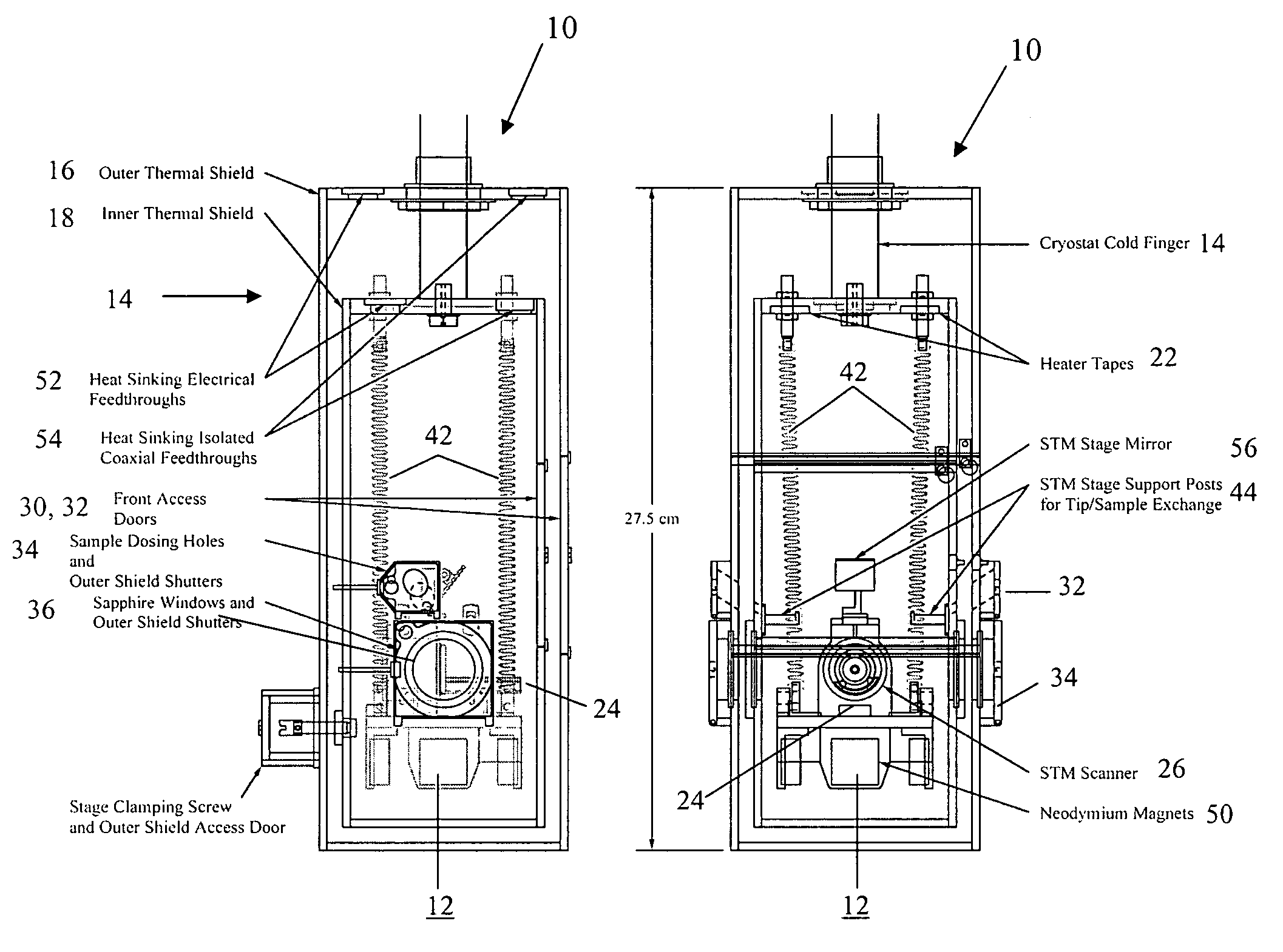
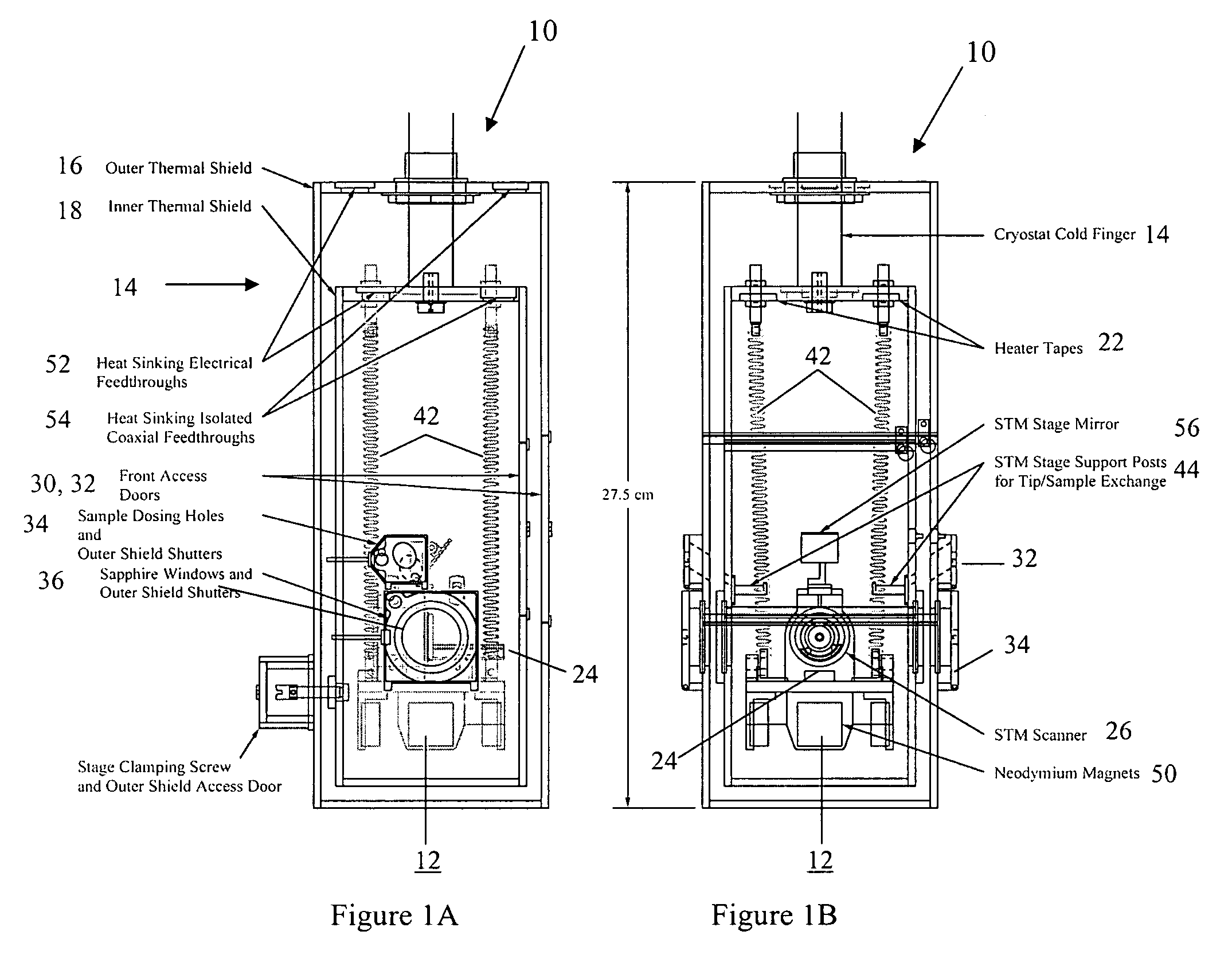
[0065]The cooling system performance between 300 and 80 K is shown in FIG. 14A. After coarse translating the sample out of tunneling range, the STM stage is clamped to the front wall of the inner thermal shield. The cryostat transfer line is inserted into the liquid nitrogen Dewar, and 30 kPa of dry nitrogen gas back pressure is applied to the Dewar. The needle valve of the transfer line inside the cryostat head and flow meter valves on the cryostat head exhaust and transfer line return are set for maximum flow. In less than 30 min, the cryogen begins to cool the assembly. Since the roof of the inner thermal shield is directly connected to the end of the cold finger, this part of the assembly begins to cool first. Shortly thereafter, the STM stage plate and STM sample holder platform follow and eventually cool at the same rate as the inner roof. When the STM stage is cooling at a maximum rate of 2.3 K / min, the separation in temperature between the STM stage and sample holder platfor...
example 2
[0066]The cooling system performance between 80 and 8.2 K is shown in FIG. 14B. The pre-cooling liquid nitrogen flow is stopped by closing the flow meter valves on the cryostat head exhaust and transfer line return while relieving the back pressure on the liquid nitrogen Dewar. Before inserting the transfer line into the liquid helium Dewar, dry helium gas is flowed through the transfer line and cryostat head to ensure that any residual liquid nitrogen and nitrogen gas are flushed from the cryostat and transfer line. When the temperature of the inner roof climbs to 80 K, the transfer line is inserted into the liquid helium Dewar, and a back pressure of 30 kPa of dry helium gas is applied. The needle and flow meter valves of the cryostat are set for maximum flow. About 1 h after the changeover to liquid helium is initiated, the temperature of the inner and outer thermal shields, which have drifted up to about 85 and 95 K, respectively, begin to cool again. When the temperature of the...
example 3
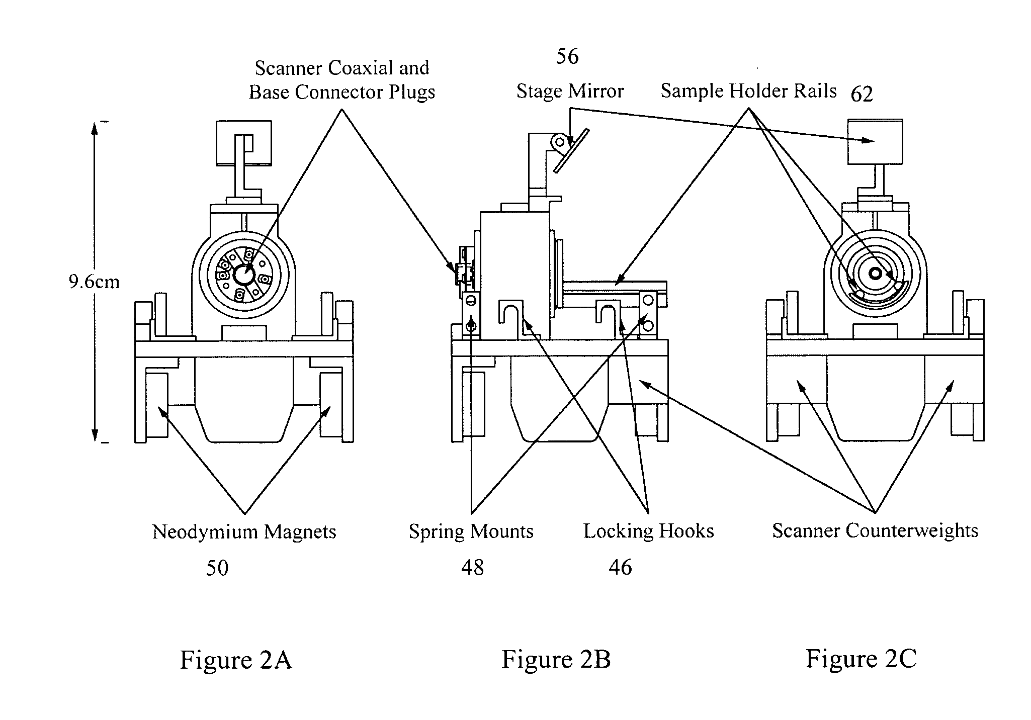
[0067]Through the use of beryllium copper for the sample holder platform and titanium nitride coated platform rails, durability in thermal cycling, thermal conductivity, and inertial translation of the sample holder at cryogenic temperatures have been improved. Thermal drift and resonant frequency characteristics are similar to that previously reported in the literature. At 8.2 K, the drift in tunneling current is less than 1.7% / min with the feedback loop disengaged. This percentage change in the tunneling current translates to a drift in tip-sample spacing of approximately 0.008 Å / min. To illustrate the insensitivity of the design to acoustic noise, it should be noted that these drift values remain unchanged even with a sustained background acoustic noise level in the laboratory up to 68 dB. The response of the piezotubes at 300 K (216 Å / V) decreases by a factor of 2.6 at 78 K (82 Å / V) and by a factor of 5.4 at 8.2 K (43 Å / V). In order to ensure adequate coarse translation of the t...
PUM
 Abstract
Description
Claims
Application Information
 - Generate Ideas
- Intellectual Property
- Life Sciences
- Materials
- Tech Scout
- Unparalleled Data Quality
- Higher Quality Content
- 60% Fewer Hallucinations
Browse by: Latest US Patents, China's latest patents, Technical Efficacy Thesaurus, Application Domain, Technology Topic, Popular Technical Reports.
© 2025 PatSnap. All rights reserved.Legal|Privacy policy|Modern Slavery Act Transparency Statement|Sitemap|About US| Contact US: help@patsnap.com


