
Capacitive electrostatic process for inhibiting the formation of biofilm deposits in membrane-separation systems

a membrane separation and electrostatic process technology, applied in the direction of separation process, membrane, centrifuge, etc., can solve the problems of reducing efficiency and failure of water treatment systems, equipment failure and maintenance challenges, and still have not prevented the formation of mineral and organic deposits, especially biofilms, on filtration membranes and wetted surfaces of water treatment plants. , to achieve the effect of preventing biofilm formation, improving membrane separation process performance, and preventing biofilm formation

Inactive Publication Date: 2009-08-25
PITTS JR M MICHAEL +1
View PDF22 Cites 9 Cited by
  • Summary
  • Abstract
  • Description
  • Claims
  • Application Information

AI Technical Summary

Benefits of technology

[0017]Another object of the invention is an improved rate of recovery in conventional membrane-separation processes.
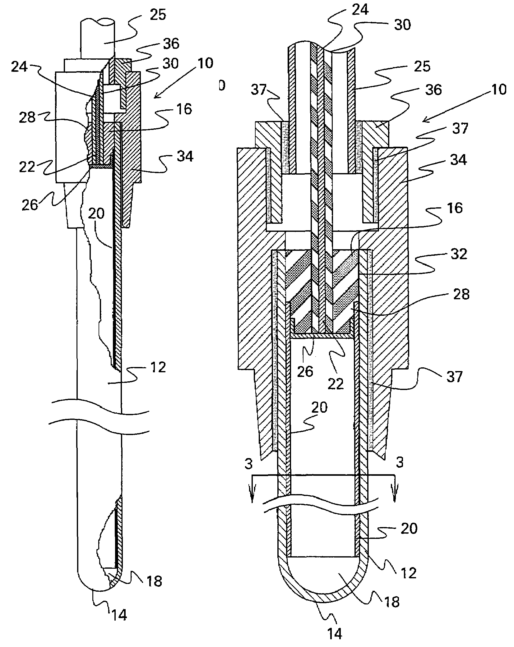
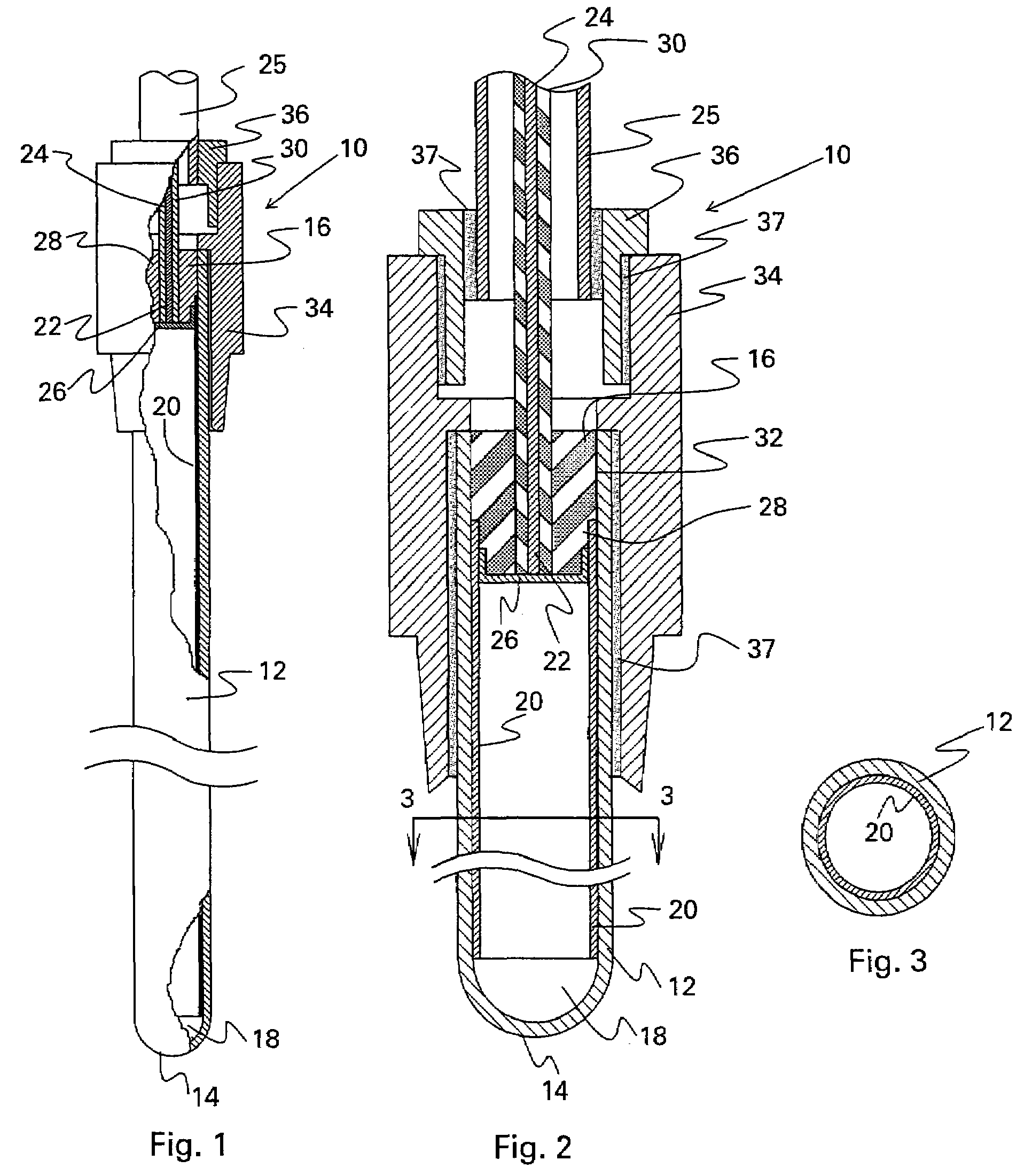
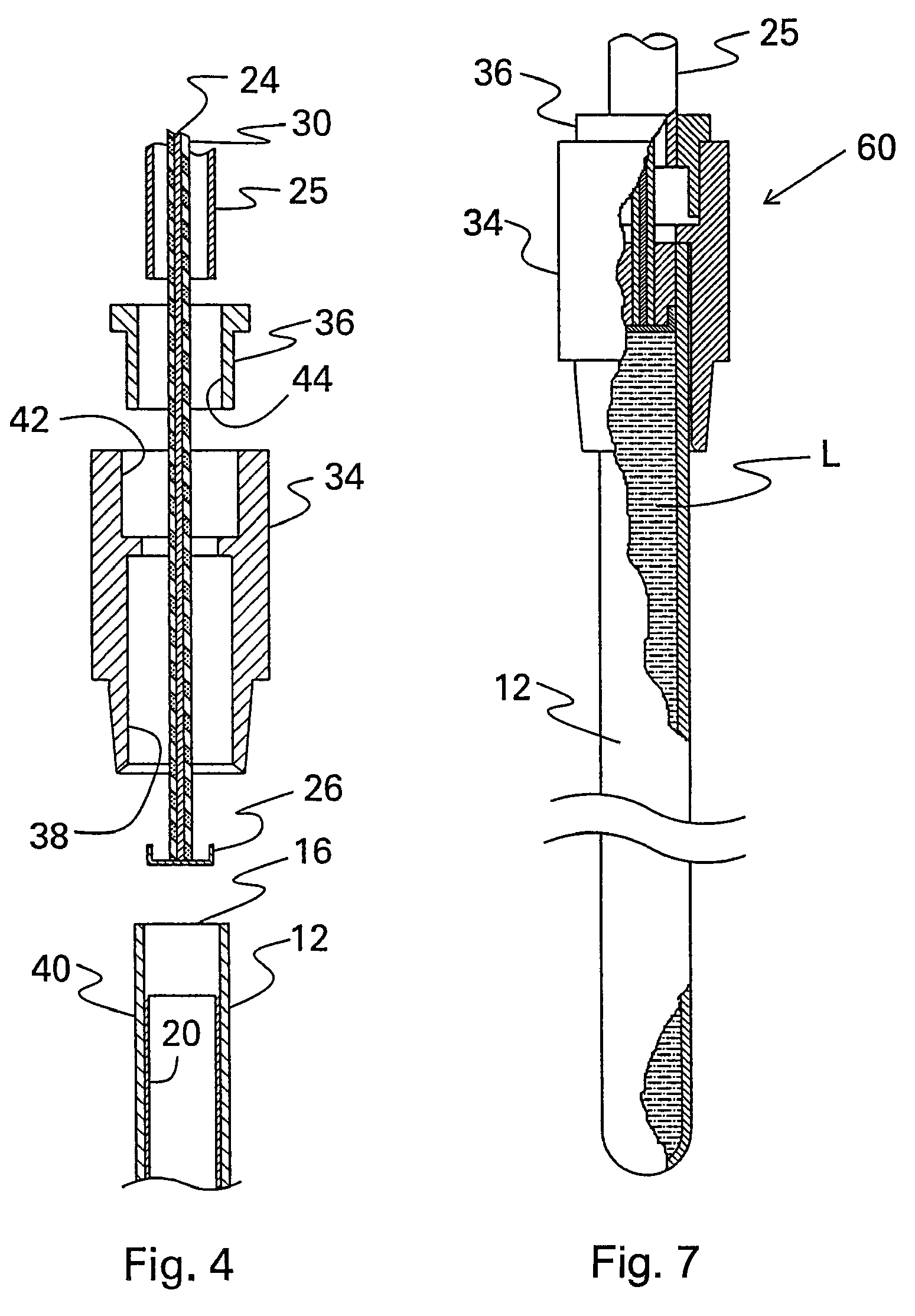
[0020]Therefore, according to these and other objectives, the present invention consists of utilizing a high-voltage capacitive electrostatic device operated at more than 10,000 volts, preferably at 30,000 and higher voltages, to prevent the formation of biofilms and correspondingly improve the performance of membrane-separation processes. The device is used in connection with conventional membrane-separation processes, particularly reverse-osmosis units, wherein species of a given ionic polarity are separated from water. The device is immersed in the water flowing across the membranes and is operated continuously at very high voltages, preferably greater than 30,000 volts DC. The charge on the wetted surface of the suspended particles is altered by the electrostatic field so generated and is found to prevent biofilm formation, thereby materially enhancing the performance of the membrane-separation system. The application of high-voltage capacitive electrostatic fields is also found to reduce corrosion of metallic surfaces in the system. The preferred embodiment of a capacitive electrostatic device for the invention is a vitrified ceramic tube of unibody construction having a single open end adapted to receive a high-voltage power cable through an insulated cap. The interior surface of the ceramic tube is lined with a layer of conductive material electrically connected to the power cable, thereby providing a relatively-large conductive surface in intimate contact with the dielectric surface of the ceramic tube.

Problems solved by technology

Water treatment systems are commonly subject to reduced efficiency and failure as a result of scaling and clogging by solid particles suspended in the aqueous medium, as well as by the formation of biofilms that adhere to exposed surfaces in the equipment.
Corrosion caused by biofilms, biosludge and scale deposits is also a source of equipment failure and maintenance challenges.
To the extent that prior-art system have been successful in facilitating the removal of suspended material, they still have not prevented the formation of mineral and organic deposits, especially biofilms, on filtration membranes and wetted surfaces of water treatment plants.
Such intimate contact is very important because any air space left between the metal and the dielectric, such as produced by blisters or bubbles in the dielectric layer, causes electrical arcing that eventually perforates the Teflon® layer, shorts the electrode to the water body, and greatly reduces the electrostatic efficiency of the device.
Moreover, a large air space would form yet another dielectric layer within the system, which is undesirable because of the very low capacitance of air which would further reduce the overall capacitance of the system.
The devices of the prior art are limited in their application by twofold problems.
Because of its well-known physical properties, PTFE material such as Teflon® is not suitable for adherence to the surface of metal conductors other than by heat-shrink processes.
Any attempt to cover an electrode with Teflon® by a process other than heat-shrinking, such as would be required for an electrode having a non-cylindrical shape, would necessarily compel the formation of seams and connections which would be very difficult to achieve and prone to breakdown during use.
In addition, due to the non-stick properties of the material, it would be very difficult to avoid the formation of air spaces between the metal and the dielectric surfaces.
Under normal stresses of operation, the connection between the tube and these end bushings has been the source of leaks which allow the water medium to come into contact with the high-voltage metallic tube and cause a complete system breakdown.
Another problem relates to the thickness of the dielectric material utilized in the prior art.
In order to optimize capacitance, the layer of Teflon® used to coat the positive electrode is kept to a minimum, thereby causing the dielectric layer to be more vulnerable to imperfections of construction which can cause arcing or other operating stresses that could result in interruption of insulation.
As a result of these constraints, the devices of the prior art are not suitable for efficient and dependable operation at voltages higher than approximately 10,000 volts, beyond which they quickly experience breakdowns.
The major problem encountered in membrane separation plants (reverse osmosis, nanofiltration, ultrafiltration) is the fouling of membranes caused by mineral, organic and biological deposits.
These deposits affect system performance because clean-water recovery and quality necessarily decline as membrane fouling increases.
In addition, the bacteria and other microorganisms entrapped on the membrane's surface cause them to become plugged, which in turn requires increased operating pressures and energy consumption, and greater frequency of chemical washing, all of which results in irreversible equipment damage.
The effect of chemicals on the formation of biofilms, though, has been very limited, both in scope and duration, providing little relief to the pervasive and enduring problem of biofilm formation and related fouling of membrane-separation units.

Method used


Image

  • Capacitive electrostatic process for inhibiting the formation of biofilm deposits in membrane-separation systems
  • Capacitive electrostatic process for inhibiting the formation of biofilm deposits in membrane-separation systems
  • Capacitive electrostatic process for inhibiting the formation of biofilm deposits in membrane-separation systems

Examples


example 1

[0062]An 18-inch ceramic electrode configured according to the device 10 and a 30 kV DC power supply were installed in the pump suction of a reverse osmosis unit at a soft drink bottling plant. The object of the installation was to study the effect of the high-voltage capacitive electrostatic field created by the device 10 on RO membranes as a means for maintaining the membranes free of biological deposits. The reverse osmosis unit in the test was an Osmonics Model OSMO 43CHF-PR216KY / DLX, having a permeate rate at 25° C. of about 450 liters per minute and a concentrate rate of about 135 liters per minute, with primary and final maximum and minimum pressures of 400 psi and 250 psi, respectively. The Osmonics unit consisted of a 3-2 series array configuration (as illustrated in FIG. 9) with each vessel housing five Filmtec membranes Model Number BW30-330. Feed water was taken from city water with about 300 ppm in total dissolved solids. Pretreatment for the water involved sand filtrat...

example 2

[0066]The capacitive electrostatic device of the invention was utilized to determine whether improvements could be obtained in a system for producing high purity water in a microelectronics plant that included two independent RO units in series. The system used an initial 2-1-1 array configuration, wherein the permeate of the first unit became the feed to a second unit having a 2-1 array, both units being equipped with Hydranautics Model 8040-LHY-CPA2 membranes. Prior to use of the electrostatic device, maintenance personnel cleaned the membranes approximately every two to three weeks. The membranes were cleaned again at the time of installation of the electrostatic device. As a part of normal feed pretreatment, a chemical dispersant was being added to the feed stream of the first RO unit. This dispersant feed was reduced by 50% after the test began.

[0067]Three weeks after the test started at about 35,000 volts DC, one vessel from each unit was opened for inspection. When the membra...

example 3

[0070]This test was conducted at a grain refinery where a permeate product for process water makeup was being produced by two independent and identical reverse-osmosis systems with a 5-3-1 configuration operating in parallel. The two RO systems shared the same water source and pretreatment system. The pretreatment consisted of a peroxide / air process to oxidize high contents of hydrogen sulfide in the water, followed by a catalytic carbon bed to remove residual sulfides, and bag filters for final polishing. The first RO unit had new membranes installed prior to the test while the second RO unit continued to operate with fouled membranes.

[0071]Fouled membranes on both units had been usually replaced every three months with clean modules, and the fouled modules were being sent out to the manufacturer for cleaning. The high voltage power supply and the electrostatic capacitor of the invention were installed and placed in operation for 27 days at 30,000 volts DC. On the sixth day of oper...


PUM

PropertyMeasurementUnit
concentrationsaaaaaaaaaa
voltagesaaaaaaaaaa
voltagesaaaaaaaaaa

Abstract

A high-voltage capacitive electrostatic device is used to improve the performance of membrane-separation processes, particularly reverse-osmosis units, wherein species of a given ionic polarity are separated from water. The device is immersed in the water flowing across the membranes and is operated continuously at very high voltages, preferably greater than 30,000 volts DC. The charge on the wetted surface of the suspended particles is altered by the electrostatic field so generated and is found to reduce biofilm formation, thereby materially enhancing the performance of the membrane-separation system. The application of high-voltage electrostatic fields is also found to reduce corrosion of metallic surfaces in the system.

Description

CROSS-REFERENCE TO RELATED APPLICATIONS[0001]This application is a continuation application of U.S. Ser. No. 10 / 796,814, filed Mar. 9, 2004 now abandoned which is a continuation of U.S. Ser. No. 10 / 047,493 (now abandoned), filed Jan. 14, 2002, which was a CIP application of U.S. Ser. No. 09 / 416,255, filed Oct. 12, 1999, abandoned, which was a CIP of 09 / 167,115 filed Oct. 6, 1998 (now abandoned), which was a CIP of Ser. No. 08 / 779,819 filed Jan. 6, 1997 (now U.S. Pat. No. 5,817,224), which as a CIP of Ser. No. 08 / 197,154 filed Feb. 16, 1994 (now U.S. Pat. No. 5,591,317).BACKGROUND OF THE INVENTION[0002]1. Field of the Invention[0003]This invention generally relates to methods for the electrostatic treatment of water streams. In particular, the invention describes a method for preventing the formation of deposits, especially biofilm deposits, on conventional membrane-separation systems by the application of a capacitive electrostatic device.[0004]2. Description of the Related Art[0005...

Claims


Application Information

Patent Timeline
Patent Type & Authority Patents(United States)
IPC IPC(8): B03C5/00B01D61/02B01D61/04B01D61/14B01D61/16B01D65/08C02F1/44C02F1/48C23F15/00C25F1/00
CPCB01D61/025B01D61/04C23F15/00B01D61/145B01D61/16B01D65/08C02F1/441C02F1/444C02F1/48B01D2311/04B01D2321/22C02F2303/04C02F2303/08C02F2303/20B01D2311/2603
Inventor PITTS, JR., M. MICHAELROMO, RODRIGO F. V.
Owner PITTS JR M MICHAEL
Learn More