Nano-scaled graphene platelets with a high length-to-width aspect ratio

a nano-scaled graphene and aspect ratio technology, applied in the field of new nano-scaled graphene platelets, can solve the problems of not being taught the length-to-thickness ratio or the length-to-width ratio of ngp, and achieve the effect of high length-to-width aspect ratio

Active Publication Date: 2010-09-07
GLOBAL GRAPHENE GRP INC
View PDF30 Cites 63 Cited by
  • Summary
  • Abstract
  • Description
  • Claims
  • Application Information

AI Technical Summary

Benefits of technology

[0028]The NGP typically has a length in the range of 1 μm to 20 μm. Using a length of 10 μm and a thickness of 1 nm as an example, we have a length-to-thickness ratio of 10,000. With a thickness of 0.334 nm (single graphene sheet) and a length of 10 μm, the length-to-thickness ratio is approximately 30,000. This is a highly desirable feature when NGPs are used as a reinforcement filler in a structural composite or as a conductive additive in an electrically conductive composite for shielding against electromagnetic interference (EMI) or radio frequency interference (RFI). It is well-known in the art of fiber reinforcements (or in the field of composite materials) that a reinforcement phase with a higher length-to-thickness ratio (a macroscopic ribbon reinforcement) or higher length-to-diameter aspect ratio (a fiber reinforcement) means a more efficient reinforcement with a higher composite strength and stiffness at a given reinforcement volume fraction. A higher aspect ratio also leads to a lower conductive filler percolation threshold, i.e., a lower volume or weight fraction of conductive additives needed to achieve a network of electron-conducting paths. However, the prior art has not taught about how the NGP length-to-width ratio or even length-to-thickness ratio would impact the behaviors of NGPs and the properties of composites containing NGPs. The instant application has demonstrated that certain properties of composites are improved when NGPs of a higher length-to-width ratio are used.

Problems solved by technology

However, the prior art has not taught about how the NGP length-to-width ratio or even length-to-thickness ratio would impact the behaviors of NGPs and the properties of composites containing NGPs.

Method used


Image

  • Nano-scaled graphene platelets with a high length-to-width aspect ratio
  • Nano-scaled graphene platelets with a high length-to-width aspect ratio
  • Nano-scaled graphene platelets with a high length-to-width aspect ratio

Examples


example 1

NGPs from PAN-Based Graphite Fibers

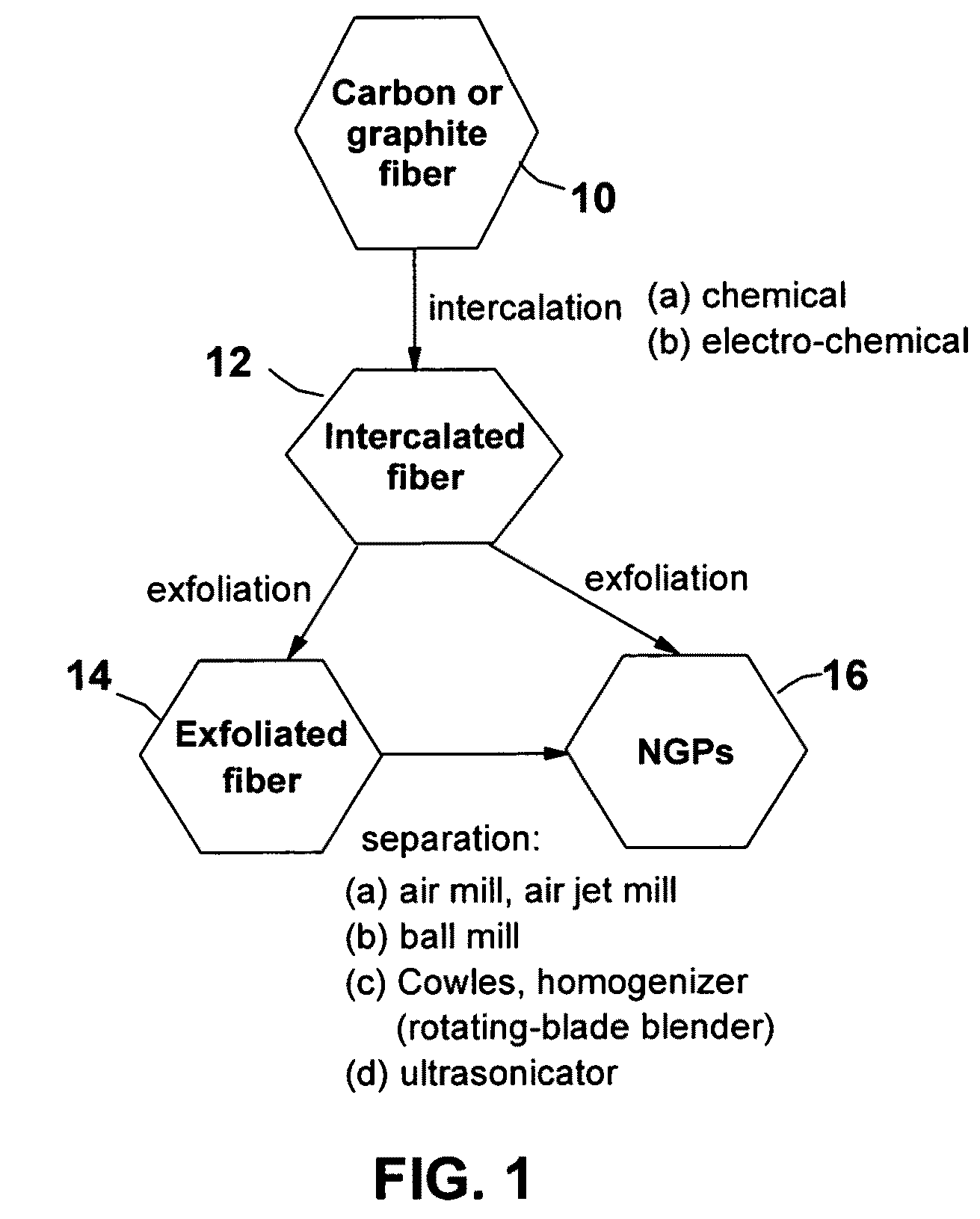
[0062]Continuous graphite fiber yarns (Magnamite from Hercules) were cut into segments of 5 mm long and then ball-milled for 24 hours. Approximately 20 grams of these milled fibers were immersed in a mixture of 2 L of formic acid and 0.1 L of hydrogen peroxide at 45° C. for 24 hours. Following the chemical oxidation intercalation treatment, the resulting intercalated fibers were washed with water and dried. The resulting product is a formic acid-intercalated graphite fiber material.

[0063]Subsequently, approximately ½ of the intercalated fiber sample was transferred to a furnace pre-set at a temperature of 600° C. for 30 seconds. The compound was found to induce extremely rapid and high expansions of graphite crystallites. Further separation of exfoliated flakes using a Cowles shearing device led to the formation of NGPs. The thickness of individual platelets was found to range from two graphene sheets to approximately 25 graphene sheets (average of...

example 2

NGPs from Sulfuric / Nitric Acid-Intercalated Pitch-Based Carbon Fibers and Nanocomposites Containing Such NGPs

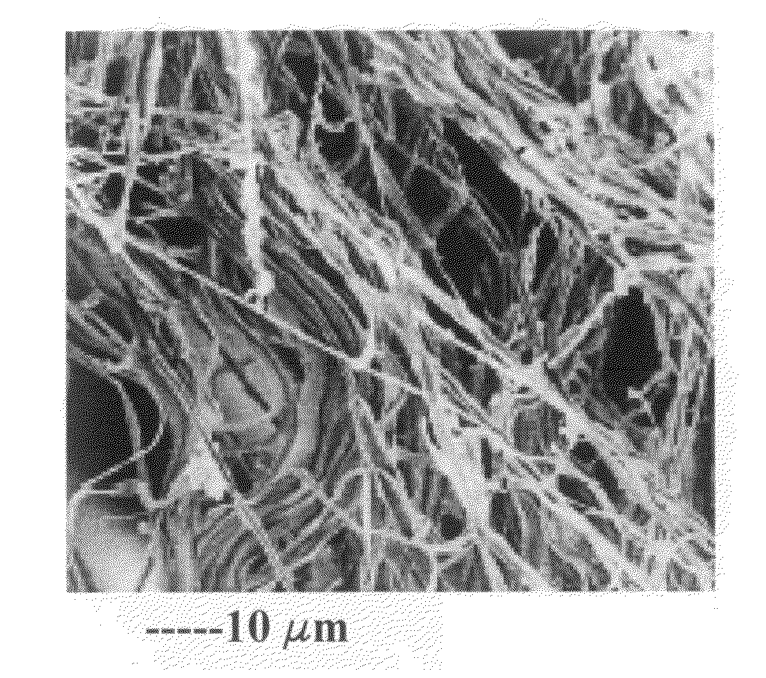
[0069]Fifty grams each of a series of carbon and graphite fibers from Amoco (P-25, P-30X, P-55S, P-75S, P-100S, and P-120S) were intercalated with a mixture of sulfuric acid, nitric acid, and potassium permanganate at a weight ratio of 4:1:0.05 (graphite-to-intercalate ratio of 1:3) for four hours. Upon completion of the intercalation reaction, the mixture was poured into deionized water and filtered. The sample was then washed with 5% HCl solution to remove most of the sulfate ions and residual salt and then repeatedly rinsed with deionized water until the pH of the filtrate was approximately 5. The dried sample was then exfoliated at 1,050° C. for 45 seconds. These samples were separately submitted to a mechanical shearing treatment in a Cowles (a rotating-blade dissolver / disperser) for 10 minutes. The resulting NGPs were examined using SEM and TEM and their length, width, ...

example 3

NGPs from Electrochemical Intercalation and Exfoliation of Carbon Fibers

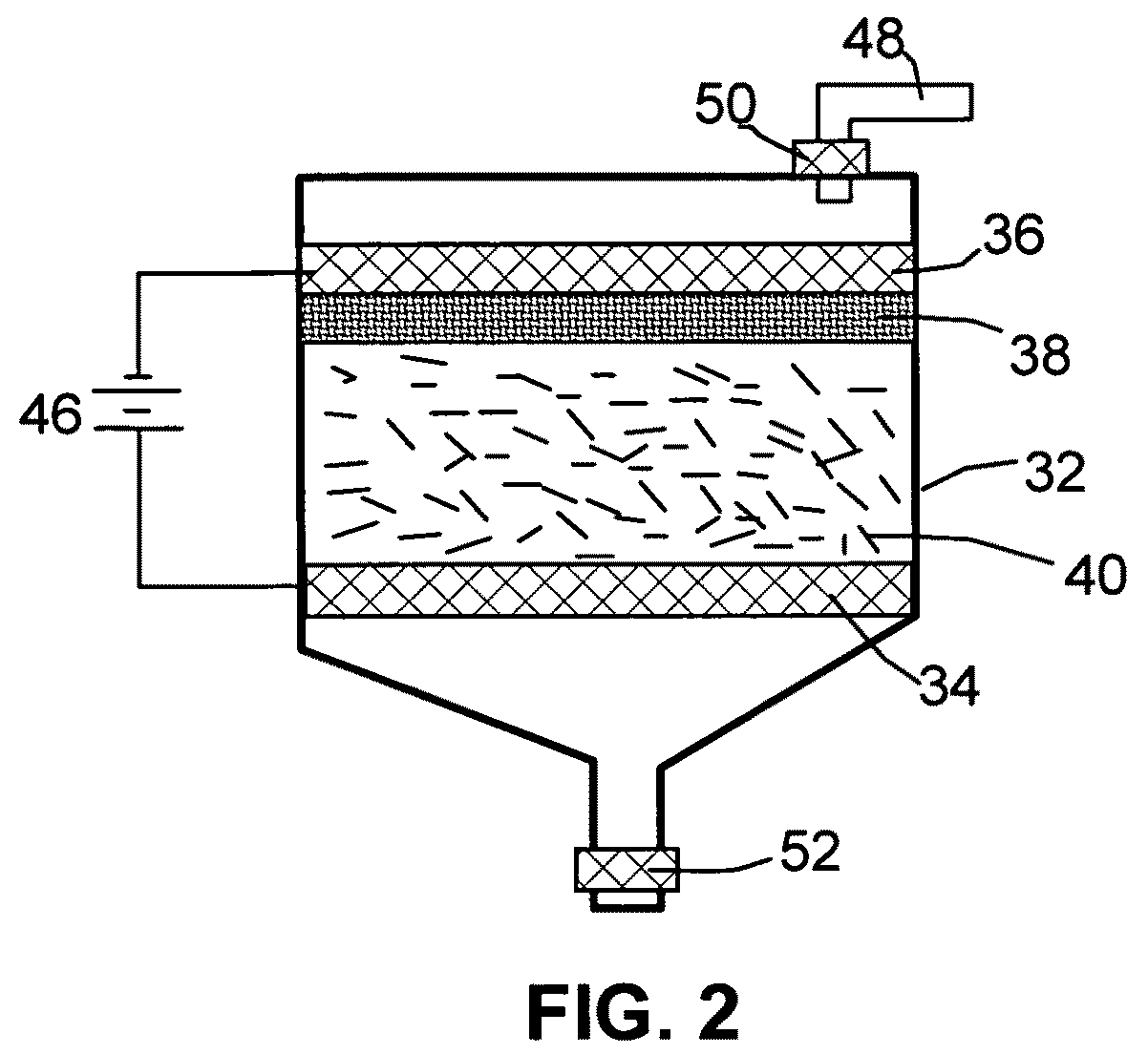
[0072]One gram of P-25 fibers, ground to approximately 220 μm in sizes, was used as the anode material and 1 L of nitric acid was used as the electrolyte and intercalate source. The anode supporting element is a platinum plate and the cathode is a graphite plate of approximately 4 cm in diameter and 0.2 cm in thickness. The separator, a glass fiber fabric, was used to separate the cathode plate from the graphite flakes and to compress the graphite flakes down against the anode supporting element to ensure that the carbon fiber segments are in electrical contact with the anode supporting element to serve as the anode. The electrodes, electrolyte, and separator are contained in a Buchner-type funnel to form an electrochemical cell. The anode supporting element, the cathode, and the separator are porous to permit intercalate (electrolyte) to saturate the graphite and to pass through the cell from top to bottom.

[007...


PUM

PropertyMeasurementUnit
thicknessaaaaaaaaaa
thicknessaaaaaaaaaa
thicknessaaaaaaaaaa

Abstract

This invention provides a nano-scaled graphene platelet (NGP) having a thickness no greater than 100 nm and a length-to-width ratio no less than 3 (preferably greater than 10). The NGP with a high length-to-width ratio can be prepared by using a method comprising (a) intercalating a carbon fiber or graphite fiber with an intercalate to form an intercalated fiber; (b) exfoliating the intercalated fiber to obtain an exfoliated fiber comprising graphene sheets or flakes; and (c) separating the graphene sheets or flakes to obtain nano-scaled graphene platelets. The invention also provides a nanocomposite material comprising an NGP with a high length-to-width ratio. Such a nanocomposite can become electrically conductive with a small weight fraction of NGPs. Conductive composites are particularly useful for shielding of sensitive electronic equipment against electromagnetic interference (EMI) or radio frequency interference (RFI), and for electrostatic charge dissipation.

Description

[0001]This invention is based on the research result of a US Department of Energy (DoE) Small Business Innovation Research (SBIR) project. The US government has certain rights on this invention.FIELD OF THE INVENTION[0002]The present invention relates to a new type of nano-scaled graphene platelets (NGPs) or graphite nano-platelets that are characterized by having a high in-plane aspect ratio (e.g., with a length / width ratio greater than 3). The invention also provides a nanocomposite comprising such NGPs as a reinforcement dispersed in a matrix material.BACKGROUND[0003]Carbon is known to have four unique crystalline structures, including diamond, graphite, fullerene, and carbon nano-tubes. The carbon nano-tube (CNT) refers to a tubular structure grown with a single wall or multi-wall, which can be conceptually obtained by rolling up a graphene sheet or several graphene sheets to form a concentric hollow structure. A graphene sheet is composed of carbon atoms occupying a two-dimensi...

Claims


Application Information

Patent Timeline
Patent Type & Authority Patents(United States)
IPC IPC(8): B32B5/16
CPCB82Y30/00B82Y40/00C01B31/0415C01B31/0469C25B1/00H05K9/009C01B2204/04C01P2004/24Y10T428/265Y10S977/773Y10S977/734Y10S977/762Y10T428/2982C01B32/22C01B32/19
Inventor ZHAMU, ARUNAGUO, JIUSHENGJANG, BOR Z.
Owner GLOBAL GRAPHENE GRP INC
Why Eureka
Try Eureka