Display element and method of driving the same

a technology of display elements and display elements, applied in static indicating devices, anthracene dyes, instruments, etc., can solve the problems of low portability, difficult to consider action as a gentle means for the human body, fatigue of eyes, etc., and achieve the effect of simple member constitution

Inactive Publication Date: 2011-09-06
KONICA MINOLTA INC
View PDF14 Cites 4 Cited by
  • Summary
  • Abstract
  • Description
  • Claims
  • Application Information

AI Technical Summary

Benefits of technology

[0039]According to the present invention, it was achieved a display element which is composed of simple constituting members and is drivable at low voltages exhibiting enhanced reflectance of white display and enhanced display speed, as well as having high stability for a change of environment of usage.THE BEST EMBODIMENT FOR EMBODYING THE INVENTION
[0040]The best mode to carry out the present invention will now be detailed.
[0041]The display element of the present invention is characterized in that an electrochromic compound colored or decolored via oxidation or reduction, a metallic salt compound, an electrolyte, and a white scattering material are incorporated between opposite electrodes; and black display, white display, and multi-color display of at least 3 colors which is colored display other than black are practically carried out by a driving operation of the opposite electrodes.
[0042]Each of the components of the present invention will now be detailed.
[0044]With regard to metallic salt compounds according to the present invention, any compounds are usable provided that these compounds are metallic species-containing salts which can be subjected to dissolution-deposition on at least one of opposite electrodes via a driving operation of the opposite electrodes. Preferable metallic species include silver, bismuth, copper, nickel, iron, chromium, and zinc. Of these, silver and bismuth are specifically preferable.
[0046]A compound containing silver according to the present invention is common designations of a compound containing silver in their chemical structure, such as silver oxide, silver sulfide, sliver halide, silver complex compound, or a silver ion. The phase states such as a solid state, a state solubilized to liquid, a gas state, and charge state types such as neutral, anionic or cationic are not particularly considered. Preferable compound for a display element of the present invention includes a well-known compound containing silver, or a compound containing silver in their chemical structure such as silver iodide, silver chloride, silver bromide, silver oxide, silver sulfide, silver citrate, silver acetate, silver behenate, silver p-toluenesulfonate, silver trifluoromethanesulfonate, silver salts with mercapto group, silver complex with iminodiacetate. Among them, a compound which does not have halogen, carbonic acid or a nitrogen atom having coordination ability with silver, for example silver p-toluenesulfonate, is especially preferable as silver salt.

Problems solved by technology

However, it is necessary to observe such the leading means for long time, particularly, when the electronic information is information of documents.
Such the action is difficultly considered as a gentle means for the human.
As the problems of such the light emission type displays, it has been known that eyes are fatigued by flicker, portability is low, posture for leading is limited and focusing on the still image is necessary and electric consumption is increased accompanied with prolongation of the leading time.
Although memory type reflective displays utilizing outside light which do not consume electric power for sustaining the image have been known as the means for compensating such the defects, such the displays are difficultly considered to have sufficient properties in the present condition by the following reasons.
In the system using a polarizing plate such as a reflective liquid crystal plate, the reflectivity is low as about 40% so that display of white image is insufficiently and majority of the production methods to be used for producing the constituting parts of the display is not always simple is utilized.
A polymer network type liquid crystal has problems that high voltage is required and a complex TFT circuit is necessary for improving the memorizing ability.
However, when sufficient black and white contrast and further colors are displayed with bright white, 3 layers of different colors need to be layered, resulting in the possibility of high cost due to a complicated element constitution.
However, in this method, high density black is unrealized due to level mixing, resulting in inadequate black and white contrast.
However, in this constitution, only 2 colors can be displayed as display colors and black display is specifically unrealized.

Method used


Image

  • Display element and method of driving the same
  • Display element and method of driving the same
  • Display element and method of driving the same

Examples


example 1

Production of Display Element 1

[0318](Preparation of Electrolytic Solution 1)

[0319]There were dissolved 0.1 g of silver iodide, 0.15 g of sodium iodide, 0.05 g of polyethylene glycol (average molecular weight: 500,000), and 0.1 g of 3,3,-dimethyl-2-(p-dimethylaminostyryl)indolino[2,1-b]oxazoline (hereinafter referred to as IRPDM) in 2.5 g of dimethyl sulfoxide to obtain electrolytic solution 1.

[0320](Production of Electrode 1)

[0321]An ITO (indium tin oxide) film of a pitch of 145 μm and an electrode width of 130 μm was formed on a glass substrate of 2 cm×4 cm having a thickness of 1.5 mm via a conventionally known method to obtain electrode 1 which was a transparent one.

[0322](Production of Electrode 2)

[0323]A silver-palladium electrode having an electrode thickness of 0.8 μm, a pitch of 145 μn, and an electrode width of 130 μm was formed on a glass substrate of 2 cm×4 cm having a thickness of 1.5 mm via a conventionally known method. This electrode was designated as electrode 2.

[03...

example 2

Production of Display Element 2

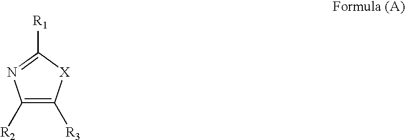
[0330]Electrolytic solution 2 was prepared in the same manner as for electrolytic solution 1 used in production of above display element 1 except that IRPDM was changed to an equimolar amount of exemplified compound 13 of Formula (A). Subsequently, display element 2 was produced in the same manner as in production of display element 1 except that electrolytic solution 1 was changed to electrolytic solution 2.

Evaluation of Display Element 2

[0331]Display element 2 was evaluated in the same manner as for display element 1 as described above. Display element 2 realized white display during no voltage application; cyan display (maximum absorption wavelength: 645 nm) during +1.5 V application; and black display during −1.5 V application. Accordingly, the results showed that multi-color display of 3 colors was realized using one type of electrolyte between a pair of opposite electrodes.

[0332]In display element 2, the overvoltage for cyan coloring was 0.8 V an...

example 3

Production of Display Element 3

[0333]Electrolytic solutions 4 and 5 were prepared in the same manner as for electrolytic solution 2 used in production of display element 2 described in Example 2 except that 0.3 g of titanium oxide was added and further exemplified compound 13 of Formula (A) was changed to an equimolar amount of exemplified compound 105 and exemplified compound 4 of Formula (A), respectively.

[0334]The peripheral portion of electrode 2 described in Example 1 was edged with an olefin-based sealing agent containing glass spherical beads of an average particle diameter of 20 μm at 10% by volume. And then a partition wall having 100 μm square windows was formed on the pixel portions intersecting with electrode 1 via photolithography to produce electrode 4. Electrolytic solutions 3, 4, and 5 were injected into the individual windows separately via Bayer arrangement using a dispenser. Further, electrode 1 was bonded at right angles to each stripe electrode to produce displa...


PUM

PropertyMeasurementUnit
reflectivityaaaaaaaaaa
temperatureaaaaaaaaaa
weight measuring methodaaaaaaaaaa

Abstract

Provided is a novel electrochemical display element which performs bright white display, high contrast black / white display and full-color display with a simple member configuration. A method for driving such display element is also provided. The display element contains an electrochromic compound, which is colored or has its color disappear due to oxidation or reduction, a metallic salt compound, an electrolyte and a white scattered material, between opposing electrodes. The display element substantially performs multiple color display of three colors or more, i.e., black display, white display and colored display other than black, by driving operation of the opposing electrodes.

Description

[0001]This is a U.S. national stage of application No. PCT / JP2007 / 073574, filed on 6 Dec. 2007. Priority under 35 U.S.C. §119(a) and 35 U.S.C. §365(b) is claimed from Japanese Application Nos. 2006-344050, filed 21 Dec. 2006, 2006-344051, filed 21 Dec. 2006, and 2007-040619, filed 21 Feb. 2007, the disclosures of which are also incorporated herein by reference.FIELD OF TECHNOLOGY[0002]The present invention relates to a novel electrochemically display element which can display multi-color by a single layer, and a method of driving the same.TECHNICAL BACKGROUND[0003]Recently, chance of getting and leading information of documents and images in a form of electronic information simpler than those in a form of usual printed material on paper is more increased accompanied with increasing in the rapidness of the processing speed of personal computer, spreading of network infrastructure and capacity glowing and cost lowering of data storage.[0004]As the means for leading such the electronic...

Claims


Application Information

Patent Timeline
Patent Type & Authority Patents(United States)
IPC IPC(8): G02F1/153G02F1/15G09G3/19G02F1/1506
CPCC09B1/00C09B5/14C09B11/02C09B11/24C09B17/00C09B19/00C09B21/00C09B23/0091C09B23/14C09B57/00C09K9/02G02F1/1506G02F1/163C07D233/64C07D263/32C07D491/048C09K2211/1007C09K2211/1033C09K2211/1037C09K2211/1044
Inventor KOKEGUCHI, NORIYUKIONO, KAORI
Owner KONICA MINOLTA INC
Why Eureka
Try Eureka