Ancillary embodiments and modifications to a polyphasic pressurized homogenizer

Inactive Publication Date: 2012-08-14
ALCHEM ENVIRONMENTAL IP
View PDF29 Cites 12 Cited by
  • Summary
  • Abstract
  • Description
  • Claims
  • Application Information

AI Technical Summary

Benefits of technology

[0066]Further, the interior configuration of the mixing chamber of the homogenizer unit may have a variety of surface textures, or conduits and ports of entry for reactive gases and/or liquids. The venturi surfaces may be smooth, textured, vaned, grooved, stepped, or have a surface configuration that enhances both mixing of the pollutant or reactant streams with additional reactants. Other vaned or grooved surfaces located below the venturi or venturis may cause the stream or streams to blend and swirl or tumble (as with stepped surfaces) so as to generate the maximum exposure and blending of the reactants to one another thereby prolonging reaction rates and times.
[0067]The rete

Problems solved by technology

Also, no methods were available to mix air-particulate or air-gas-particulate streams that were of a polluting nature that caused such streams to be entrained in an aqueous medium or matrix under pressure that were intended for biodegradation.
Air-sparging is adequate to serve as a mixing device, but is very limited as to enhancing chemical substitutions or reactions.
Simple mixing by stirring can readily result in inadequate blending or long-term blending that expends equipment and funds due to the difficulty of achieving uniform mixing or homogenization.
Since the mixing devices are constantly subjected to corrosive environments, breakage and system failures are frequent and require back-up or redundant tanks to hold the liquids being treated in order to recover ‘lost’ equipment and repair the system.
One drawback is the tendency of hydrophobic particulates, liquids, or vapors (oily or greasy gas or gases) to resist wetting in varying degrees.
Adding a surfactant may simply result in some portion of the pollutants becoming ‘wet’ while other components remain on the surface of the water droplets or film.
Another major drawback or shortcoming is the size ('footprint') of the scrubber.
The expense, energy demands, and manpower input required to operate and maintain such a device or devices may be pro

Method used


Image

  • Ancillary embodiments and modifications to a polyphasic pressurized homogenizer
  • Ancillary embodiments and modifications to a polyphasic pressurized homogenizer
  • Ancillary embodiments and modifications to a polyphasic pressurized homogenizer

Examples


example 1

[0144]The homogenizer unit and ancillary embodiments lends itself to the safe and effective removal of both hazardous and non-hazardous particulates from the atmosphere and to their entrainment into an aqueous matrix, thereby rendering such particulates harmless and in a contained situation that is inherently safe.

[0145]Passing a large volume of dust-laden or contaminated air through an homogenizer unit (that is properly grounded to prevent static electricity buildup and subsequent discharge) forces the entrained particulates to become ‘wetted’ simply by forced contact with the homogenizer embodiments. If deemed necessary and more efficacious than water, a suitable surfactant or other agent that enhances wetting and surface tension reduction will be introduced into the water. Contaminated air is depured (=purified) to a very high degree (that approaches complete removal of particulates), thereby releasing cooled, humidified, particulate-free air back into the atmosphere from which t...

example 2

[0147]Serial placement of homogenizer units including the aforementioned ancillary embodiments may or will result in the segregation of a certain entrained gas or gases, pollutant or pollutants from internal combustion engines, furnaces other than electric units, smelter and metal crafting discharges, or other combustion sources while allowing that same gas or gases to pass into serially-arranged reaction vessels or vessels in parallel or having a variety of configuration or configurations. In this application or these applications, removal of a certain pollutant or pollutants may be adequate to allow the gas passing into the terminal reaction vessel or homogenizer unit or units to be depured (=purified) so as to render that gas or gases suitable to be containerized for some means of disposition.

[0148]For example, a mixed stream of pollutants containing carbon dioxide (CO2), carbon monoxide (CO), particulates (PMs), ammonium ion (NH3), nitrogen oxides (NOx), sulfur oxides (SOx), and...

example 3

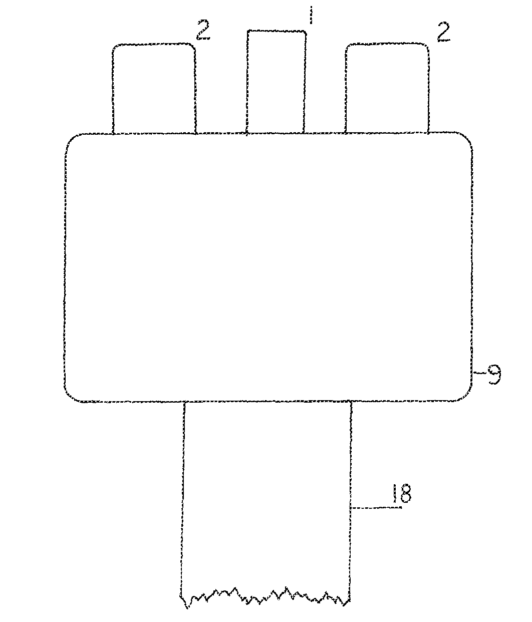
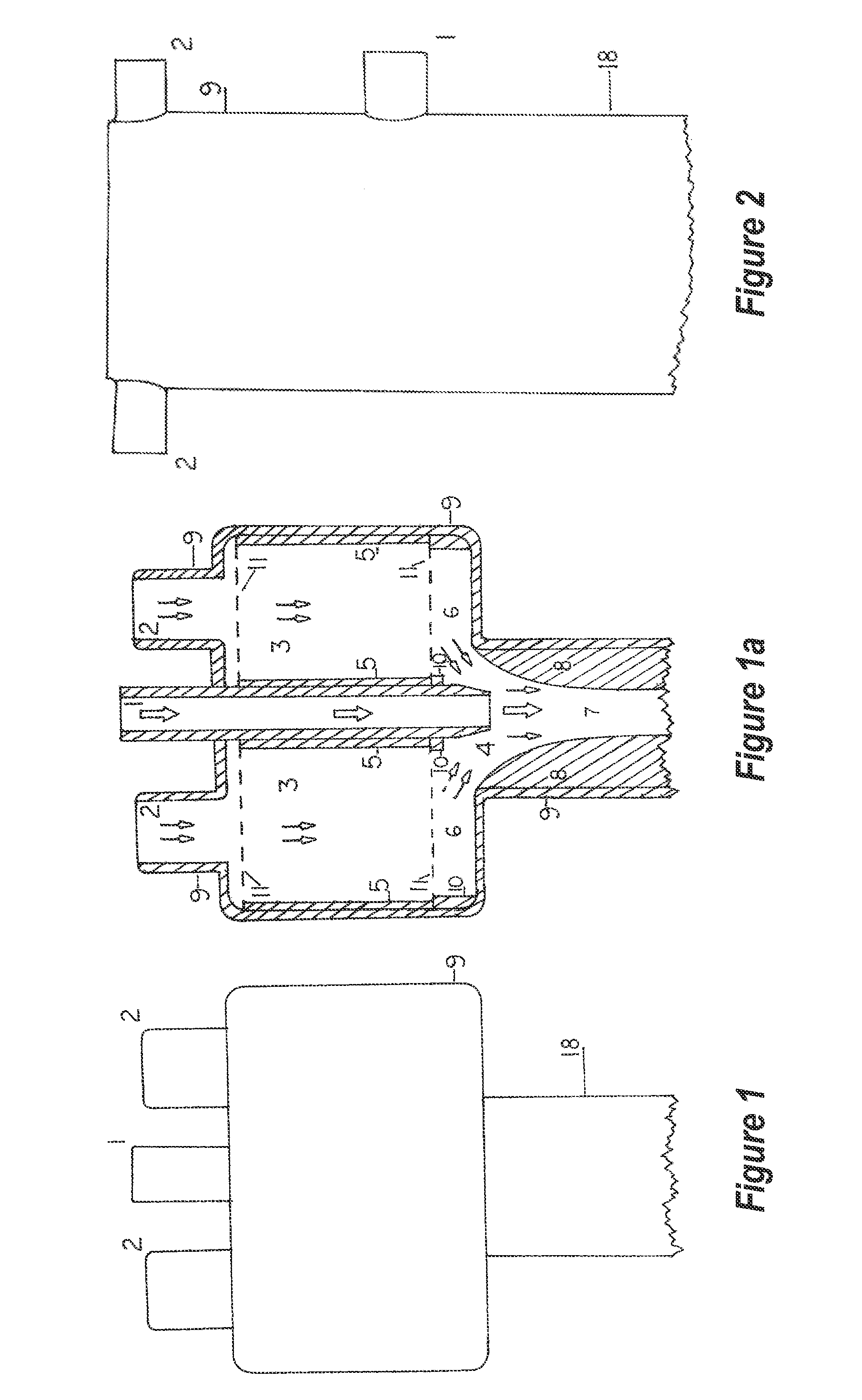
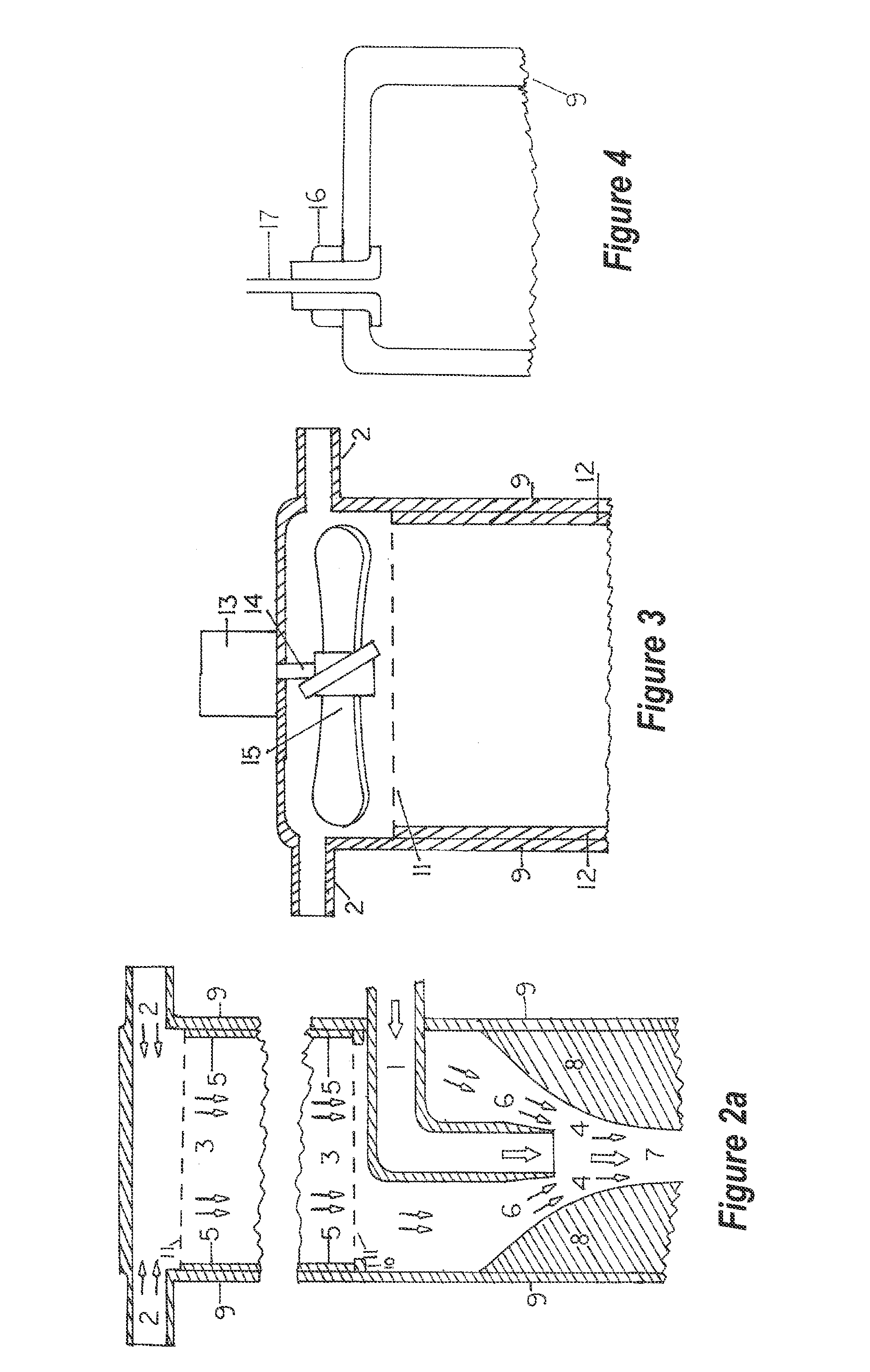
[0177]Embodiments to the homogenizer unit, comprising:

[0178]a magnetic particulate removal device stationed in line with the homogenizer conduit,

[0179]an ante-mixing chamber embodiment having one or more ‘packings’ that is contained within the homogenizer unit,

[0180]a jet or battery of similar jets, each having the ability to conduct a single solvent or any combination of solvents to the venturi cone within the homogenizer unit,

[0181]a venturi within the homogenizer unit, having a variety of embodiments relating to its surface treatments that may or will enhance the reactions between the solvent or solvents and the targeted pollutants,

[0182]a detention chamber embodiment that is a continuous conduit with the homogenizer unit. This chamber may have a variety of internal configurations or devices that further enhance reactions between the reactant(s) and the targeted pollutants,

[0183]a discharge tube or tubes or other devices as embodiments at the lower terminus of the retention chamb...


PUM

PropertyMeasurementUnit
Pressureaaaaaaaaaa
Diameteraaaaaaaaaa
Diameteraaaaaaaaaa

Abstract

Ancillary embodiments and modifications to a homogenizer unit that increases its applicability to a wide spectrum of chemical or physical-chemical reactions and properties. Methods of introducing reactants and devices that present a tortuous pathway to reactants are placed at a strategic locus (or loci) that delay or modify flow pathways to gases, liquids, aerosols, particulates, or any combination thereof. Reactions of a chemical, physical-chemical, and thermo-chemical nature between a wide variety of matter are possible and readily achieved with the correct solvent(s), reactant(s), or pressure under controlled conditions of pressure, temperature, chemical concentrations, and other impingements. Various well-recognized or established principles are used to expedite reactions. These include ‘Boyle's Gas Law’, surface-to-volume relationships, anion and cation substitutions, heat absorption by water, gas solubility factors, stoichiometric chemistries, surface tension reactions, dissolution constants, and others.

Description

CROSS-REFERENCE TO RELATED APPLICATION[0001]The present application claims the benefit of U.S. Patent Application Ser. No. 61 / 106,256, filed Oct. 17, 2008, entitled “ANCILLARY EMBODIMENTS AND MODIFICATIONS TO A POLYPHASIC PRESSURIZED HOMOGENIZER”, the disclosure of which is incorporated by reference in its entirety.1. FIELD OF THE INVENTION[0002]The present ancillary modifications and embodiments significantly enhance the effectiveness of the extant invention, U.S. Pat. No. 6,001,155 (incorporated herein by reference), so as to enable the device to include chemical and physico-chemical reactions beyond that of the original intentions. Included within these reactions, but not limited to them, are the substitution of anions of the alkali and alkali-earth metals, ammonia, and other metallic and non-metallic elements and compounds.[0003]The invention and the ancillary embodiments and modifications also have the ability to isolate, recombine, and cause reactions to occur between or among...

Claims


Application Information

Patent Timeline
IPC IPC(8): B01D47/00
CPCB01D47/10B01D47/025B01F5/0415B01F5/043B01F5/0604B01F5/0606B01F5/0647B01F5/0655B01F5/0695B01F3/02B01F3/04503B01F2005/0436B01D53/18B01D53/78B01D2251/30B01D2251/40B01D2252/103B01D2257/708B01D2257/90B01D2257/91B01D2258/06B01D2259/4508B01F23/10B01F23/2323B01F25/3121B01F25/312512B01F25/31243B01F25/422B01F25/4231B01F25/4331B01F25/4338B01F25/4524
Inventor PEASE, JOHN R.BLATNICK, JOHN F.
Owner ALCHEM ENVIRONMENTAL IP
Why Eureka
Try Eureka