Method for manufacturing thin film transistor using multi-tone mask

a technology of multi-tone masks and thin films, applied in non-linear optics, instruments, optics, etc., can solve the problems of affecting production, yield, manufacturing cost, etc., and achieve the effect of reducing the number of light-exposure masks, and simplifying the photolithography process

Active Publication Date: 2012-08-14
SEMICON ENERGY LAB CO LTD
View PDF173 Cites 119 Cited by
  • Summary
  • Abstract
  • Description
  • Claims
  • Application Information

AI Technical Summary

Benefits of technology

[0006]A thin film transistor including an oxide semiconductor in a channel formation region has higher field-effect mobility than a thin film transistor including amorphous silicon. An oxide semiconductor film can be formed at temperatures of 300° C. or lower by a sputtering method or the like and a manufacturing process of a thin film transistor including an oxide semiconductor film is simpler than that of a thin film transistor including polycrystalline silicon.
[0008]As a method for manufacturing a thin film transistor, a method by which a stacked structure is formed by a photolithography process using a number of light-exposure masks (also referred to as photomasks) is employed. However, a photolithography process includes a number of steps and is one factor of largely affecting the manufacturing cost, yield, productivity, and the like. In particular, reducing the number of light-exposure masks whose design and manufacturing costs are high is a significant object.
[0009]In view of the above problems, it is an object to manufacture a semiconductor device at low cost with high productivity in such a manner that a photolithography process is simplified by reducing the number of light-exposure masks.
[0011]Since a mask layer formed using a multi-tone mask has a plurality of thicknesses and can be further changed in shape by performing etching, the mask layer can be used in a plurality of etching steps to provide different patterns. Therefore, a mask layer corresponding at least two kinds of different patterns can be formed using one multi-tone mask. Thus, the number of light-exposure masks can be reduced and the number of corresponding photolithography processes can also be reduced, whereby simplification of a manufacturing process can be realized.
[0016]Since an In—Ga—Zn—O-based non-single-crystal film is formed by a sputtering method and then subjected to thermal treatment at 200° C. to 500° C., typically 300° C. to 400° C. for 10 minutes to 100 minutes, an amorphous structure is observed as its crystal structure in an XRD (X-ray diffraction) analysis. Moreover, as for the electrical characteristics of the thin film transistor, an on / off ratio of 109 or more and a mobility of 10 or more at a gate voltage of ±20 V can be achieved.
[0030]Further, by reducing the number of light-exposure masks, a photolithography process is simplified, whereby a reliable semiconductor device can be manufactured at low cost with high productivity.

Problems solved by technology

However, a photolithography process includes a number of steps and is one factor of largely affecting the manufacturing cost, yield, productivity, and the like.

Method used


Image

  • Method for manufacturing thin film transistor using multi-tone mask
  • Method for manufacturing thin film transistor using multi-tone mask
  • Method for manufacturing thin film transistor using multi-tone mask

Examples


embodiment 1

[0062]A method for manufacturing a semiconductor device of this embodiment is described with reference to FIGS. 1A to 1E and FIGS. 2A and 2B.

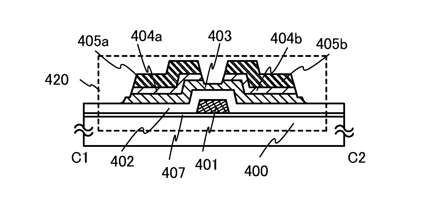
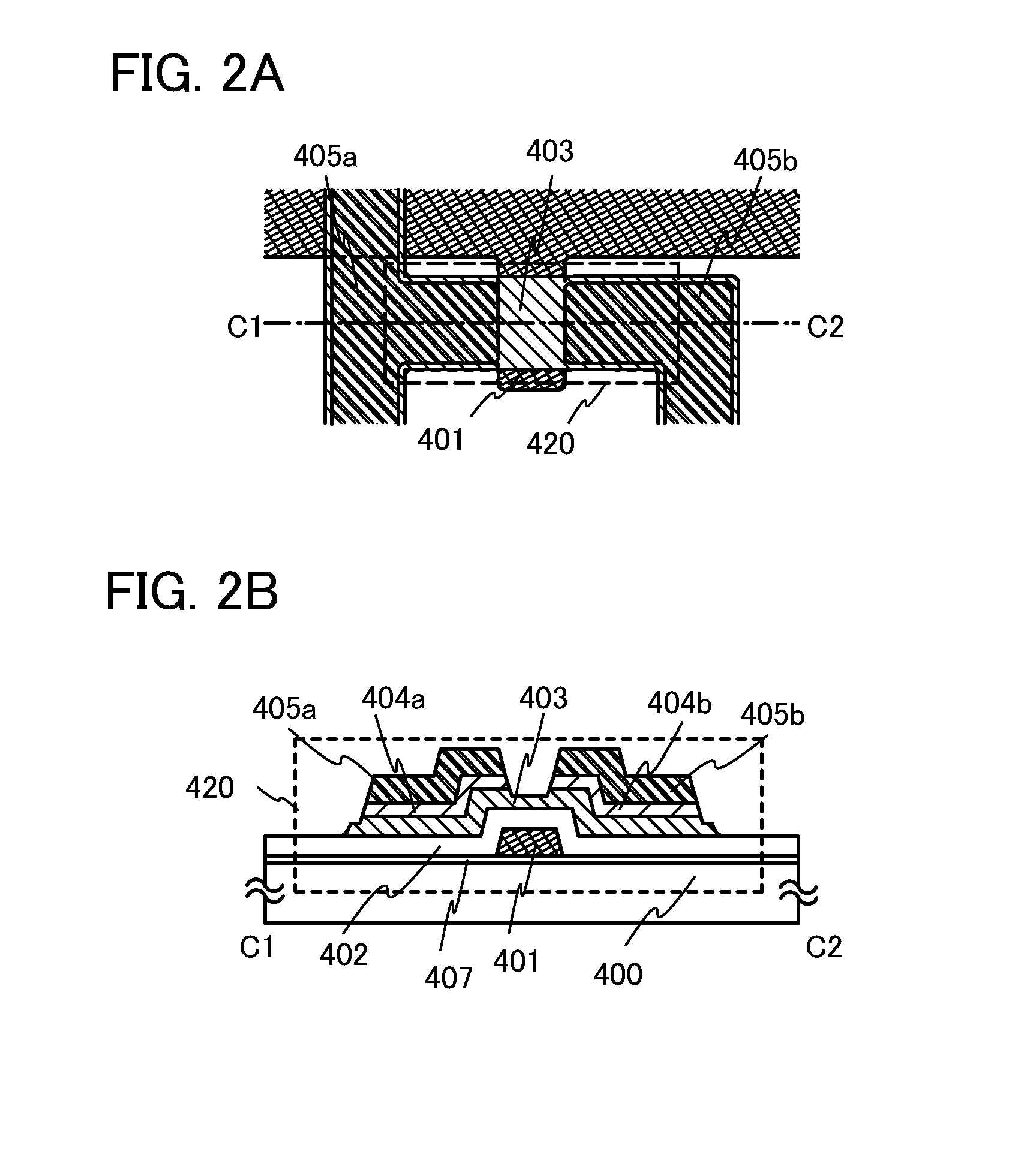
[0063]FIG. 2A is a plan view of a thin film transistor 420 of a semiconductor device of this embodiment, and FIG. 2B is a cross-sectional view taken along C1-C2 of FIG. 2A. The thin film transistor 420 is an inverted staggered thin film transistor and includes a gate electrode layer 401, a gate insulating layer 402, a semiconductor layer 403, n+ layers 404a and 404b serving as a source region and a drain region, and source and drain electrode layers 405a and 405b.

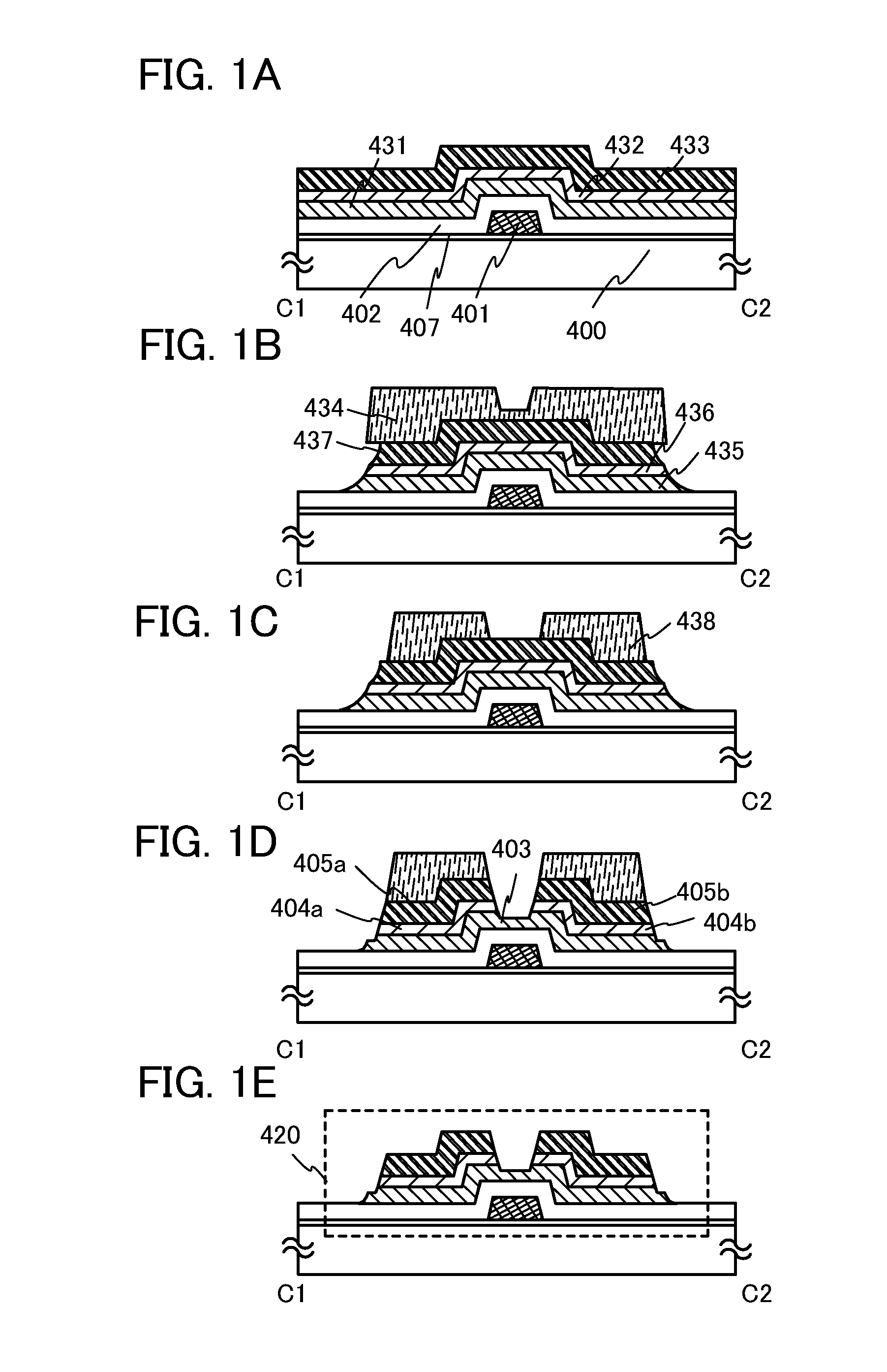
[0064]FIGS. 1A to 1E correspond to cross-sectional views illustrating steps of manufacturing the thin film transistor 420.

[0065]In FIG. 1A, an insulating film 407 serving as a base film is provided over a substrate 400 and the gate electrode layer 401 is provided over the insulating film 407. The insulating film 407 has a function of preventing diffusion of an impurity element from th...

embodiment 2

[0115]Here, an example of a semiconductor device including a thin film transistor with a structure where the source and drain electrode layers are in contact with the semiconductor layer in Embodiment 1 is described with reference to FIGS. 3A to 3E and FIGS. 4A and 4B.

[0116]FIG. 4A is a plan view of a thin film transistor 460 in a semiconductor device of this embodiment, and FIG. 4B is a cross-sectional view taken along D1-D2 of FIG. 4A. The thin film transistor 460 is an inverted staggered thin film transistor and includes a gate electrode layer 451, a gate insulating layer 452, a semiconductor layer 453, and source and drain electrode layers 455a and 455b.

[0117]FIGS. 3A to 3E are cross-sectional views illustrating steps of manufacturing the thin film transistor 460.

[0118]In FIG. 3A, an insulating film 457 serving as a base film is provided over a substrate 450 and the gate electrode layer 451 is provided over the insulating film 457. In this embodiment, a silicon oxide film (with...

embodiment 3

[0149]In this embodiment, a process for manufacturing a display device including a thin film transistor is described with reference to FIGS. 5A to 5C, FIGS. 6A to 6C, FIG. 7, FIG. 8, FIG. 9, FIG. 10, FIGS. 11A, 11B, 11C, and 11D, and FIG. 12.

[0150]As for a substrate 100 having a light-transmitting property illustrated in FIG. 5A, a glass substrate of barium borosilicate glass, aluminoborosilicate glass, or the like which is typified by #7059 glass, #1737 glass, or the like manufactured by Corning, Inc. can be used.

[0151]Next, a conductive layer is formed entirely over a surface of the substrate 100, and then a first photolithography process is performed to form a resist mask. Then, an unnecessary portion is removed by etching, so that wirings and electrodes (a gate wiring including a gate electrode layer 101, a capacitor wiring 108, and a first terminal 121) are formed. At this time, the etching is performed so that at least an end portion of the gate electrode layer 101 is tapered....


PUM

PropertyMeasurementUnit
temperaturesaaaaaaaaaa
gate voltageaaaaaaaaaa
diameteraaaaaaaaaa

Abstract

An object is to manufacture a semiconductor device including an oxide semiconductor at low cost with high productivity in such a manner that a photolithography process is simplified by reducing the number of light-exposure masks. In a method for manufacturing a semiconductor device including a channel-etched inverted-staggered thin film transistor, an oxide semiconductor film and a conductive film are etched using a mask layer formed with the use of a multi-tone mask which is a light-exposure mask through which light is transmitted so as to have a plurality of intensities. In etching steps, a first etching step is performed by wet etching in which an etchant is used, and a second etching step is performed by dry etching in which an etching gas is used.

Description

BACKGROUND OF THE INVENTION[0001]1. Field of the Invention[0002]The present invention relates to a semiconductor device including an oxide semiconductor, and a manufacturing method thereof.[0003]2. Description of the Related Art[0004]A thin film transistor formed over a flat plate such as a glass substrate is manufactured using amorphous silicon or polycrystalline silicon, as typically seen in a liquid crystal display device. A thin film transistor manufactured using amorphous silicon has low field-effect mobility, but such a transistor can be formed over a glass substrate with a larger area. On the other hand, a thin film transistor manufactured using crystalline silicon has high field-effect mobility, but a crystallization step such as laser annealing is necessary and such a transistor is not always suitable for a larger glass substrate.[0005]In contrast, attention has been drawn on a technique in which a thin film transistor is manufactured using an oxide semiconductor and applie...

Claims


Application Information

Patent Timeline
Patent Type & Authority Patents(United States)
IPC IPC(8): H01L29/786G02F1/1368H01L21/3065H01L21/336H01L51/50H05B44/00
CPCH01L27/1225H01L29/78621H01L29/66742H01L27/1288H01L29/66969H01L29/7869H01L27/1214
Inventor SUZAWA, HIDEOMISASAGAWA, SHINYAMURAOKA, TAIGAITO, SHUNICHIHOSOBA, MIYUKI
Owner SEMICON ENERGY LAB CO LTD
Why Eureka
Try Eureka