Weir design providing optimal purge gas flow, melt control, and temperature stabilization for improved single crystal growth in a continuous Czochralski process

a technology of purge gas flow and continuous czochralski, which is applied in the direction of crystal growth process polycrystalline material growth, etc., can solve the problems of increasing cycle time, increasing melt equilibration time, and increasing cycle time, so as to prevent slumping or distortion of weirs, increase path length and transit time, and limit the introduction of impurities

Active Publication Date: 2012-09-11
CORNER STAR LTD
View PDF5 Cites 59 Cited by
  • Summary
  • Abstract
  • Description
  • Claims
  • Application Information

AI Technical Summary

Benefits of technology

[0020]Another aspect of the invention provides a double weir arrangement, wherein first and second weirs define an outer and inner melt region, respectively, separated from the growth region. One or more submerged, flow controlling passageways provided in the weirs control the flow of melt from outer melt region to the inner melt region and into the growth region. The weir passageways effectively increase the path length and transit time for molten silicon feedstock to ensure complete melting of all particles in the melt.
[0021]A further aspect of the invention provides a labyrinthine flow path between the growth region and the melt region for an inert gas such as argon. Materials for the labyrinth are selected to withstand the high temperature, reactive environment without contributing impurities to the melt. The exit from the labyrinth is designed to optimally distribute the argon gas flows over the surface of the melt to sweep away silicon oxides evolved from the melt into the exhaust manifold system, preventing those oxides from depositing on critical surfaces from which they could drop down into the melt as particles which would lead to dislocation and other defects in the growing single crystal structure.
[0022]Another aspect of the invention provides a double weir arrangement including a devitrification promoter applied to the outer surfaces of the weirs to form a ceramic shell that provides mechanical reinforcement and prevents slumping or distortion of the weirs. Such a coating advantageously limits the formation and detachment from the weir or weirs of cristabolites as well as limits the introduction of impurities into the melt. The devitrification promoter applied

Problems solved by technology

In the case of batch recharge, increased cycle time is particularly significant when feedstock must be added in solid form, and this disadvantageously can add up to several hours of equilibration time to the growth cycle.
Addition of liquid feedstock particularly in batch recharge reduces the melt equilibration time, but involves the considerable design complications and increased cost of a pre-melter.
A disadvantage of a Czochralski continuous or batch recharge crystal growth is that silicon dust and un-melted particles of silicon, whether from a pre-melter or resulting from the addition of solid feedstock into the melt, are transferred into the melt and growth chamber and can become attached to the growing ingot causing it to lose its single crystal structure.
The particles and dust can then fall into the melt and cause dislocations in the growing ingot.
However, smaller size chips of feedstock are characterized by greater surface area to volume.
Thus, the preferred use of such small feedstock material exacerbates the problems of dust.
Unfortunately, these small size distributions are characterized by relatively high levels of small particles and dust which readily can become airborne.
At silicon process temperatures, silicon oxide formed by dissolution of the quartz crucible evaporates from the melt and condenses on slightly cooler areas of the hot zone to form a powder or dust that may become a serious maintenance problem.
When this powder or dust falls b

Method used


Image

  • Weir design providing optimal purge gas flow, melt control, and temperature stabilization for improved single crystal growth in a continuous Czochralski process
  • Weir design providing optimal purge gas flow, melt control, and temperature stabilization for improved single crystal growth in a continuous Czochralski process
  • Weir design providing optimal purge gas flow, melt control, and temperature stabilization for improved single crystal growth in a continuous Czochralski process

Examples


Embodiment Construction

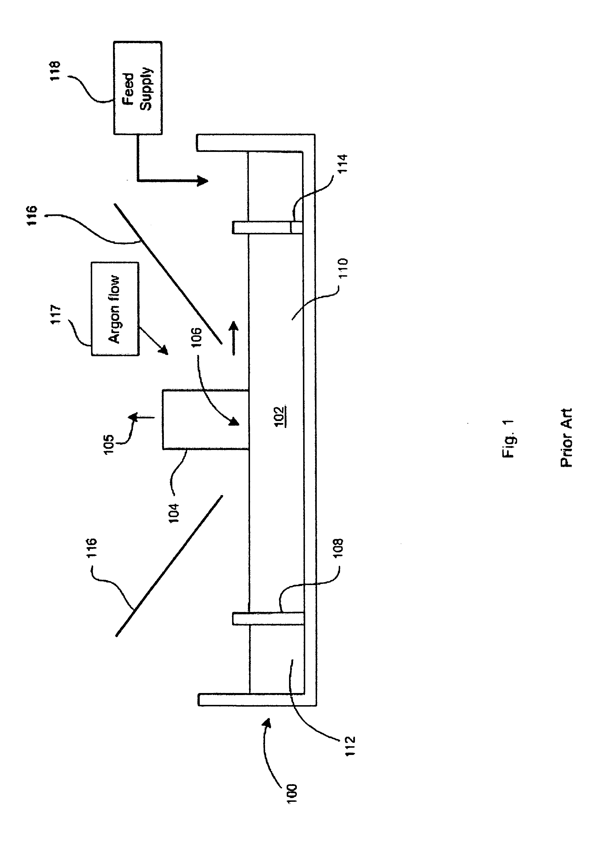
[0033]Referring to FIG. 1, in a conventional Czochralski system, a crucible 100 holds a quantity of molten silicon 102 in which a single crystal ingot 104 is grown and pulled in a vertical direction indicated by arrow 105 from a crystal / melt interface 106 as is well known. A weir 108 typically comprising a quartz cylinder is positioned on the floor of the crucible 100 and extends vertically above the melt as shown.

[0034]The weir 108 defines an inner growth region 110 and an outer melt supplementing region 112. One or more subsurface passageways 114 connect the first or melt supplementing region 112 with the inner growth region 110.

[0035]A heat shield 116 is typically conical in shape and depends downwardly at an angle to create an annular opening disposed about the growing crystal or ingot 104 to permit the growing ingot to radiate its latent heat of solidification and thermal flux from the melt The top of the heat shield has a first diameter much wider than the diameter forming the...


PUM


Abstract

A weir is extended vertically to define an optimal annular gap between the top of the weir and the underside of a super-adjacent heat shield. The annular gap provides a high velocity stream of argon gas to be directed from the growth region to the melt region to substantially eliminate the transport of airborne particles from the melt region to the growth region. The tall weir may be configured as a modular, reusable weir extension supportably engaged with an outer (and/or inner) weir.

Description

CROSS-REFERENCE TO RELATED APPLICATION[0001]This patent application claims the benefit of U.S. provisional patent application Ser. No. 60 / 906, 945, filed Mar. 13, 2007.BACKGROUND[0002]1. Field of the Invention[0003]The field of the invention relates generally to growing single crystal semiconductor material by the Czochralski process. In particular, the field of the invention relates to a continuous Czochralski process employing a tall weir comprising optionally a second weir providing a double weir. The tall weir extends vertically and is configured for providing an optimal flow and velocity of an inert gas, such as argon, to be directed away from the crystal growth region to the melt region, thereby preventing airborne particles or other contaminants from causing dislocations or related defects in the growing single crystal structure. The double weir's function is to properly melt unmelted particles of silicon by ensuring sufficient transit time and optimal crystal growth conditio...

Claims


Application Information

Patent Timeline
IPC IPC(8): C30B21/02
CPCC30B29/06C30B15/002C30B15/12Y10T117/1068Y10T117/1072
Inventor BENDER, DAVID L.SMITH, DAVID E. A.
Owner CORNER STAR LTD
Why Eureka
Try Eureka